Hunting mobile devices endpoints - the RF and the Hard way
Vous souhaitez améliorer vos compétences ? Découvrez nos sessions de formation ! En savoir plus
When conducting intrusion tests, knowledge of endpoints and exchanged data is mandatory to test targeted applications, devices, and remote servers. If the target provides an Android, or iPhone application, it is possible to extract some URLs, and with any luck some secrets by disassembling the application or/and capturing the generated network traffic.
But when no Android nor iPhone applications are available, attackers need to be more creative, and use other tricks to get any interesting inputs/content/behavior. Moreover, secrets exchanged between a targeted device and its servers could be totally different from those exchanged between an application and its servers, as well as contacted URLs.
Indeed, pentesters are in certain cases confronted to devices with hardcoded credentials, certificates, or any other information giving further access to intrude the system. In addition, the level of trust could be overestimated by vendors/constructors, who give more privileges to devices compared to basic users. So breaking into the device or/and directly intercepting its communication could be a real change during intrusion tests.
This article is about getting those information from IoT devices that use the mobile network to exchange data and commands. Different techniques will be introduced:
- RF way: use of mobile data interception techniques;
- Hard way: dump and analysis of a firmware.
To illustrate these attacks, examples will be based on a 3G intercom well deployed in France, which is powered with a PIC24FJ micro-controller.
Requirements
To practice the hardware way, here are the following requirements:
- 1 Microchip PICkit 3 In-Circuit Debugger - https://www.microchip.com/Developmenttools/ProductDetails/PartNo/PG164130. But if your targeted device has any other interface like JTAG, SPI, UART or whatever, you can look for other interface connectors like Shikra/Bus Pirate, Arduino/ESP/Raspberry pi/Odroid/Tinker/etc GPIOs, and so on;
- 1 multimeter for continuity testing (a good one, and not very expensive like the 'Extech EX330');
- 5 male jumper wires.
For the Radio Frequency (RF) way:
- A BladeRF, or USRP, or any other motherboard that is supported by YateBTS, or OpenBTS;
- Modmobmap + a supported device to scan 2G, 3G and 4G cells;
- Modmobjam to jam automatically from Modmobmap results;
- (optional) A metal case, something like the M&Ms 1Kg metal case minimum, and aluminum foil tape;
- (optional) A custom SIM card like sysmoSIM card one, or a prepaid SIM card from another country that is not allowed to roam in your country.
For both:
- A big cup of coffee! Because this article is a little long;
- A famous 3G intercom, preferably one using a Microchip micro-controller supported by the PICkit 3, if you want to practice with the PICkit 3 debugger;
- Or any other device using the mobile network and that connects to a web server also works.
Anyway, if you are ever interested in practicing or not, maybe these couple of sounds will keep you in the good mood during this reading:
Context: finish the unfinished
Almost two years ago, we published several results regarding widely deployed (in most capitals in Europe anyway) House Intercoms that use the mobile network. The first House intercoms attacks presentation took place at the Nuit du Hack 2016 where we showed how GSM intercoms could be attacked in practice with a good interception infrastructure using YateBTS (or OpenBTS) and a 'cheap' Software-Defined radio hardware like bladeRF (~400€).
Then at Hack.lu 2016, some advancements have been presented on the 3G intercoms that could be attacked after a downgrading attack. In addition to downgrading attacks, we have shown these intercoms are all connected to a central server to stay synchronized.
These intercoms use the following Machine-2-Machine mobile network architecture.
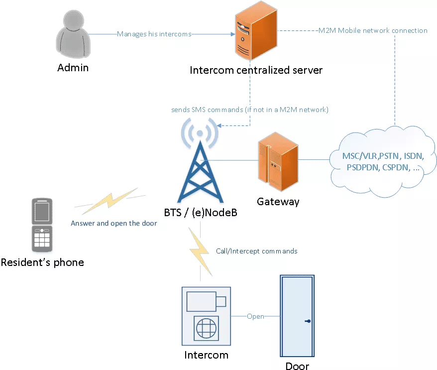
As discussed at Hack.lu 2016 and also 33c3, any vulnerability found in this server, or any third party connected to this server, would give interesting access for an attacker that would be able to open an important number of frontdoors at the same time. During this talk we also showed a vulnerability that enabled us to control a large amount of intercoms remotely with just a simple internet connection. Moreover, the vendor provides a valid M2M SIM card with 10 years validity that is used by the intercom to connect to internet. That M2M SIM card is protected by a PIN that can be recovered with a SIMTRACE tool, and then plugged in a phone to tether the connection. In some contexts, this connection will give further accesses to the vendor virtual mobile network by using the right APN (Access Point Name).
In 2017, we have continued to present on intercoms at OSSIR meeting, by completing the presentation with additionnal vectors a pentester may encounter dealing with physical accesses like the provided RF remote and the VIGIK (RFID) parts. At the end of each of our intercom talk, we tried to answer those who asked questions as clearly as possible. Moreover, some answers to these questions where also published in a form Proof of Concepts we have just presented this year.
The questions were the following:
- How do you perform 3G and 4G cell monitoring as osmocomBB do with 2G? Answer: Modmobmap
- How do you perform jamming attacks on targeted cells? Answer: "smart" jamming with Modmobjam
- How do you jam 3G signal as it is known to be resistant to interferences? Answer: the jamming margin in M-ary-SS, Direct Sequence Spread Spectrum (DSSS), and Orthogonal Frequency Division Multiplex (OFDM) used by 3G systems has a level of acceptable interference. So any level of noise greater than this thresold will hide the targeted cell from the mobile equipment with noise.
But other questions were also asked:
- Did you look at the hardware, dumped the flash and extracted some secrets?
- How did you retrieve the Access Point Name (APN) used by this device?
- Did you find interesting endpoints to attack?
Those three questions were also answered briefly between beer sessions. But the real reason behind this blog post is that we have encountered interesting contexts during some of our intrusions tests, so we wanted to share some techniques that could be useful when attacking this kind of IoT devices, and that pentesters or "Red Teamer" may encounter today: connected electric counters, connected cars, delivery pick-up stations, and so on.
And to illustrate these techniques, we continued to peel the last intercom we have presented almost 2 years ago.
The target
The target is a 3G intercom from a very common vendor used in France, as shown in the following picture.
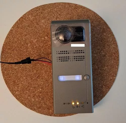
For those who recognize it, the targeted model is the "cheapest" one (merely 2000€) that only works for one resident. What we are looking for are the endpoints contacted by the intercom and, with any luck, the data exchanged between the device and servers.
To achieve this task, we will use two different techniques:
- The wireless (RF) way;
- And then the hardware way.
The wireless way
If the intercom supports 3G and if there is a such network available, it will preferably choose 3G, and contact the web servers to synchronize itself. To run our own mobile network, many solutions exist like the Amarisoft LTE solution made by Fabrice Bellard, and a free one like srsLTE. But in 3G, the Universal Subscriber Identity Module (USIM) is ready for mutual authentication, and so actual baseband normally checks it to protect the user equipment from establishing hazardous connections to rogue NodeB and eNodeB. The official way to let a device connect to our own NodeB or eNodeB is to use a custom USIM card but rare exceptions could be found when using an old SIM card for 3G networks, or a device with a defective/badly implemented baseband that skip the mutual authentication. For more information about strange and crazy basebands behaviors, you can read an interesting paper presented at SSTIC 2014 in French by Benoit Michau. In addition to defective baseband implementations, roaming based tricks exist, but need an operator access that could be expensive (e.g: Signalling System No. 7).
So our main problem as an attacker is to impersonate a mobile network, and to capture its data exchanged between the targeted device and the network. To do so, we will show 3 different techniques that allow us to isolate a device. Choosing one appropriate technique will give us the chance to attract the target, and then capture its data for further analysis.
Caution
Remember that most of the presented RF techniques are illegal, and you are responsible for your actions by practicing them. To avoid any problem, be sure to impact only your own equipment by lowering the transmission power as much as possible.
Environment set-up
The chosen set-up is the same as presented in our different talks about intercom attacks. It is composed of a bladeRF and a computer that run a rogue GSM base station with YateBTS. Cheaper alternatives also exist but are not documented in this article (e.g. running a BTS with a LimeSDR mini with the OsmoTRX software).
The following configuration is clearly explained in GPRS part of YateBTS wiki.
In the case of 3G intercoms, the capture of data exchanged with remote servers is mandatory, so the GPRS should be activated in YateBTS configuration file ybts.conf as follows:
...
[gprs]
Enable=yes
...
The configuration relative to the Gateway GPRS Support Node is also needed. This will handle exchanges between our GPRS network and our Internet connection. The configuration can look as follows:
...
[ggsn]
DNS=8.8.8.8 8.8.4.4 ; its preferable to use your own servers for client side attacks
IP.MaxPacketSize=1520
IP.ReuseTimeout=180
IP.TossDuplicatePackets=no
Logfile.Name=/tmp/sgsn.log
MS.IP.Base=192.168.99.1
MS.IP.MaxCount=254
TunName=sgsntun
Then as usual, we have to tell the kernel to allow IP forwarding, and then iptables to forward the traffic from the internal network:
# echo 1 > /proc/sys/net/ipv4/ip_forward
# iptables -A POSTROUTING -t nat -s 192.168.99.0/24 ! -d 192.168.99.0/24 -j MASQUERADE
This configuration allows to register to our fake GPRS network with a mobile phone by scanning operators, and registering the cellphone to the network.
Note: If the BTS (Base Transceiver Station) is running with a Mobile Country Code (MCC) and Mobile Network Codes (MNC) codes different from the one associated to our SIM/USIM card operator, it will be necessary to activate the itinerary feature (as it is already the case with Free Mobile users for example) to allow data on the created network, or change the codes to correspond to your SIM/USIM card operator.
Once the running BTS correctly configured, the mobile phone be then able to browse the Internet. This is indicated with the tiny icon showing the phone is actually connected througt GPRS.

The platform is ready for intercepting data, but some elements must be considered to attract our target successfully.
Ways to attract the target
As stated above, the intercom will always try to connect to a valid 3G network first.
To circumvent this known behavior, 3 different directions could be undertaken to elevate our chances to attract the device:
- Downgrading the 3G communication and force the device to communicate in GSM/GPRS;
- Using a sort of faraday cage to isolate the device from legitimate mobile networks;
- Using a custom SIM card to force the device to register to our rogue base station.
These techniques are explained below.
Note: different frequency ranges have to be tested in order to increase chances of seeing your target connecting to your network. Indeed, baseband or devices that command them perform some non-deterministic optimizations when scanning frequencies. For example, some devices need to send a lot of data, so high frequencies like 1800-1900 MHz are preferred. Some others look mostly on lower frequencies for long distances.
Method 1 - Downgrade attacks with "smart" jamming
Downgrade attacks can sometimes be tricky but are necessary if the device is mainly looking for 3G or 4G existent signals. So in most cases, attackers will not be able to isolate the targeted device as wanted.
A basic method would be to buy a cheap 2G/3G/4G jammer, and rework it to drown all 3G and 4G signals. But cleaner ways exist, like one we have presented earlier this year: the "smart" jamming (or "targeted cells jamming" is a less classy name).
To perform a "smart" jamming attack, two steps have to be followed in a respective order:
- Monitor and collect cells and their Download/Upload Absolute Radio-Frequency Channel Number (ARFCN);
- Jam precise frequencies associated to collected ARFCNs of (the) targeted operator(s).
Monitoring cells with Modmobmap
As presented at BeeRump 2018, many independent methods could be used to retrieve the list of 2G, 3G, 4G cells. Unfortunately, not one allowed to get it with only one tool and hardware before. So we choose to develop Modmobmap that is able to retrieve a list of surrounding 2G, 3G, and 4G cells with a simple Samsung phone (other supports will come with time).
For this article, we will use a compatible rooted Samsung Galaxy S5 with Modmobmap running on a host computer to get the list of every possible cells.
After cloning the repository and installing all dependencies, we connect the Samsung Galaxy S5 to the computer and enable ADB. Then, we launch Modmobmap as follows on the host computer:
$ sudo python modmobmap.py -m servicemode -s <Android SDK path>
* daemon not running; starting now at tcp:5037
* daemon started successfully
=> Requesting a list of MCC/MNC. Please wait, it may take a while...
[+] New cell detected [CellID/PCI-DL_freq  (XXXXXXXXX)]
 Network type=2G
 PLMN=208-20
 ARFCN=1014
Found 3 operator(s)
{u'20810': u'F SFR', u'20820': u'F-Bouygues Telecom', u'20801': u'Orange F'}
[+] Unregistered from current PLMN
=> Changing MCC/MNC for: 20810
[+] New cell detected [CellID/PCI-DL_freq  (XXXXXXXXXX)]
 Network type=2G
 PLMN=208-20
 ARFCN=76
[+] New cell detected [CellID/PCI-DL_freq  (XXXXXXXXXX)]
 Network type=2G
 PLMN=208-10
 ARFCN=76
=> Changing network type for 3G only
[+] New cell detected [CellID/PCI-DL_freq  (XXXXXXXXXX)]
 Network type=3G
 PLMN=208-10
 Band=8
 Downlink UARFCN=3075
 Uplink UARFCN=2850
=> Changing network type for 2G only
=> Switching back to auto-mode
[+] Unregistered from current PLMN
=> Changing MCC/MNC for: 20820
[+] New cell detected [CellID/PCI-DL_freq  (XXXXXXXXXX)]
 Network type=3G
 PLMN=208-10
 Band=8
 Downlink UARFCN=3075
 Uplink UARFCN=2850
=> Changing network type for 3G only
[+] New cell detected [CellID/PCI-DL_freq  (XXXXXXXXXX)]
 Network type=4G
 PLMN=208-20
 Band=3
 Downlink EARFCN=1675
[+] New cell detected [CellID/PCI-DL_freq  (XXXXXXXXXX)]
 Network type=4G
 PLMN=208-20
 Band=1
 Downlink EARFCN=251
=> Changing network type for 2G only
=> Switching back to auto-mode
[+] Unregistered from current PLMN
=> Changing MCC/MNC for: 20801
=> Changing network type for 3G only
[+] New cell detected [CellID/PCI-DL_freq  (XXXXXXXXXX)]
 Network type=3G
 PLMN=208-1
 Band=8
 Downlink UARFCN=3011
 Uplink UARFCN=2786
[...]
[+] Cells save as cells_1536076848.json # with an CTRL+C interrupt
As we can see, a list of cells is saved in cells_1536076848.json file when the user decides to interrupt the tool. This file could be then interpreted by any other tool, including a "smart" jamming tool called Modmodjam for example.
Jamming with Modmobjam
During a rump session at SSTIC this year, we presented a complementary technique to our tool Modmobmap called "smart" jamming. This presentation was then followed with the announcement of a tool called Modmobjam we have developed to isolate a device from precise operators.
After cloning the repository of Modmobjam, we can see two important scripts that will be used to perform the automated jamming attack.
The first script is GRC/jammer_gen.py generated by the GnuRadio Companion schema designed in GRC/jammer_gen.grc. If this tool is used with a HackRF, or any transmitter depending on the osmocom sink block, it is possible to run directly the GRC/jammer_gen.py script as follows:
$ python GRC/jammer_gen.py
If your transmitter does not depend on osmocom sink block, you can still rebuild the GRC/jammer_gen.py script with by modifying the provided GnuRadio Companion schema.
The GRC/jammer_gen.py can be commanded manually from its GUI to jam a desired frequency, to change the gain, to change the bandwidth, and so on. But this script could be also commanded by a client to jam cells automatically. For this purpose, the second script smartjam_rpcclient.py aims to send commands through RPC and accepts the JSON file generated by the Mobmobmap tool. Assuming the operator we need to jam is "Orange", we can simply use this last script by providing the MCC and MNC codes of the respecting Public Land Mobile Network (PLMN) filter as follows:
$ python smartjam_rpcclient.py -f <Modmobmap path>/cells_1536076848.json -w 208-1
[+] Jamming cell XXXXX-XXXX central frequency at 942.2 MHz with 10 MHz bandwidth
[...]
After few minutes, we should be able to attract the intercom to our rogue GSM/GPRS BTS, as the device does not see any 3G "Orange" cells around anymore but just noise instead at reserved channels.
Note that the delay between two cell jamming session can be defined with parameter -d to tell the tool to be more or less aggressive.
In same cases, jamming efforts could be avoided by using a kind of Faraday cage or a custom SIM/USIM card.
Method 2 - Faraday cage: or something similar and cheap
In short, the Faraday cage is a well known concept to protect equipment from electric noise and charge but from electromagnetic noise. This concept is also used to avoid external pollution of a device. The term Faraday cage is also known as electromagnetic shielding for radio waves like the mobile signal, but are less easy to make than Faraday cage against electrical charges. To attenuate or block signals, the shielding material and conception depends on several elements:
- Frequency;
- Wavelength;
- Power of reception or transmission;
- Distance between the receiver and the transmitter.
It is really important to consider all those elements before choosing the material as well as the design. For example, if you opt for a cage with meshes, windows should be optimised against the electric field for reflection. Moreover, mobile devices change frequencies in 2G/3G/4G and it is a behavior we have to be aware of. For box shielding, the magnetic permeability and also the thickness of the material is important.
Searching on internet, you will be tempted to buy one of the commercial RF/EMI shield. But this comes with an expensive price and will not be easy to carry (heavy and cumbersome). Moreover, in our case we are not interested to get a very high tempest quality shielding container. Indeed, something that would significantly attenuate the signal from mobile base stations is enough. So here comes the metal M&M's box!

From experience, if you put your phone on a good metal box and close the lid for few seconds, the cellphone will loose the signal from base stations around.
Once you have eaten all of the M&Ms, the complete bladeRF can fit in the box, but it is recommended to only put antennas is this box to keep some space inside. Note that it is important that the seal between the lid and the box is tight and consolidated with aluminum foil tape, and any holes covered with the same foil tape. Before putting the targeted device in the box with the running BTS, YateBTS's configuration has to be changed to avoid any damage on the receiving side. To do so, we have to lower down the parameter Radio.PowerManager.MaxAttenDB of ybts.conf to the minimum and increment the value by step until it is detected by the targeted device.
Sometimes, the targeted device won't fit in the box. So here is what we did with the intercom by including an external antenna:
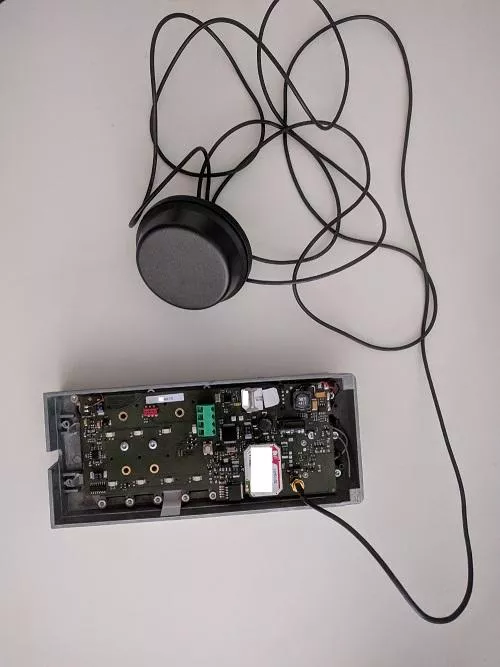
With this intercom the position of a switch close to the antenna must be flipped to use the external antenna.
The final set-up should look like this:
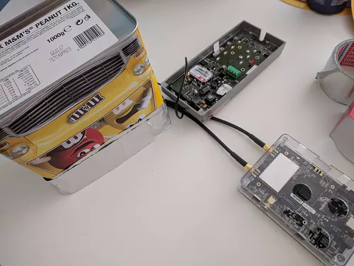
This Faraday M&Ms box works really great in our case, but in other contexts the use of a custom SIM/USIM card could be also be efficient and less tricky.
Method 3 - Using a custom SIM/USIM card
In some cases, the access to the SIM/USIM card is not possible or very hard (e.g: current Sierra modems). But when it is possible, this method should be considered first, because it excludes the user equipment from contacting any legit operator. This could save any missed packet sent on a initialization state of the device for example.
Generally, prepaid USIM/SIMs card from other countries that do not accept roaming could work to perform the isolation. But you can also opt for a sysmo SIM/USIM card made to be freely programmed.
Caution: some devices are forcing Personal Identity Number (PIN) code typing. In that case, it is recommended to sniff the PIN typed by the device with a SIMTRACE, as presented our talks since Hack.lu 2016. That would prevent your custom SIM/USIM card from being blocked, and typing a PUK (Personal Unblocking Code) code to unlock it.
Note also that in this case, it is also possible to use a rogue (e)NodeB capture the data in 3G, or 4G without problem. But we will stick to our GSM/GPRS BTS for this article.
Capturing and analyzing GPRS data
Once the target is trapped on our network, we will be able to capture its data exchanged with other servers.
By using one of the isolation method above, we are able to trap the device on out network, and intercept its communications.
For example, we can observe in the following capture that our network associated a Temporary Mobile Subscriber Identity (TMSI) with the targeted International Mobile Subscriber Identity (IMSI):
nipc list registered
IMSI            MSISDN
--------------- ---------------
20801XXXXXXXXXXXX   69691320681
We can also get the information in the SGSN Mobile Station list:
mbts sgsn list
 GMM Context: imsi=20801XXXXXXXXXXXXX ptmsi=0xd3001 tlli=0xc00d3001 state=GmmRegisteredNormal age=5 idle=1 MS#1,TLLI=c00d3001,8d402e2e IPs=192.168.99.1
Note that an IP address 192.168.99.1 was assigned by our network. Meaning that the device is ready to send data and contact servers.
Capturing the GSMTAP queries, it is possible to get the APN used by the device as follows:
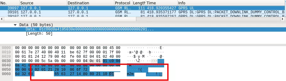
By capturing the traffic with Wireshark on the tun interface created for the SGSN, in our case sgsntun, it is possible to intercept messages exchanged between the intercom and servers on Internet:
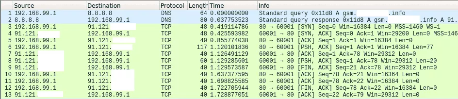
In the capture, it is possible to notice that only 2 different TCP ports are queried on a unique server to synchronize our intercom. Queries on port TCP 60001 seems to be dedicated to clock synchronization. Indeed, when requesting the service as follows multiple times, we get the current time:
In [1]: import socket
In [2]: import binascii
In [3]: ip = '91.121.XXX.XXX'
In [4]: port = 60001
In [6]: s = socket.socket(socket.AF_INET, socket.SOCK_STREAM)
In [7]: s.connect((ip, port))
In [8]: s.send(binascii.hexlify("011e4d25636014006600000000000000090000011e1540XX[...]"))
Out[8]: 320
In [9]: data = s.recv(1024)
In [10]: data
Out[11]: '2018/09/07 15:09:01\n'
By looking at the devices stickers, it is possible to notice the ID number of the intercom is included in the requests (in the little endian format 1540XX) as follows:
So our supposition is that only this number identify the device from others. But for this particular service, impersonating an intercom is not really interesting.
Looking at captures, we can observe the port 55556/tcp is also running a service on the same remote server. With this intercom, the payload sent for the service 55556/tcp is the same as 60001/tcp we mentioned earlier. But on this last port, changes on the administration web panel have to be made to make talk to the intercom. This data is potentially generated to update the intercom. However, the data sent by this service is not really clear:
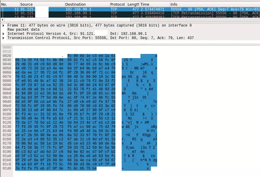
Analyzing quickly the payload with ent, the payload sent by the server for updates seems to be encrypted:
$ ent payload.hex
Entropy = 7.371044 bits per byte.
[...]
As capturing encrypted payloads is not the end of the road, we can turn to the hardware to make sense of those binary blobs.
Hopefully, by analyzing its firmware, we can identify the algorithm and key used.
But for this part we already got what we wanted to illustrate: the interception of queries and responses by our targeted device.
As said earlier, the data captured on GPRS between the device and its control server could include a lot of interesting things including credentials, or authentication token to a service, etc.
Moreover, several network attacks like faking servers are also interesting to perform for client side attacks.
In some cases network scans could also be performed to discover running services in the targeted device. But as far as we know, this last case in rare and requires the targeted device to be more complex, packed with features, and use a more powerful architecture.
So that was the way to hunt for mobile endpoints using a rogue GPRS base station. Let's see now how we could try to do the same thing with hardware attacks, and without the use of the rogue BTS.
Hardware way
Identification
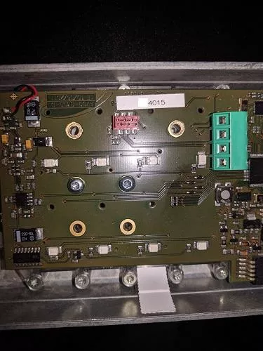
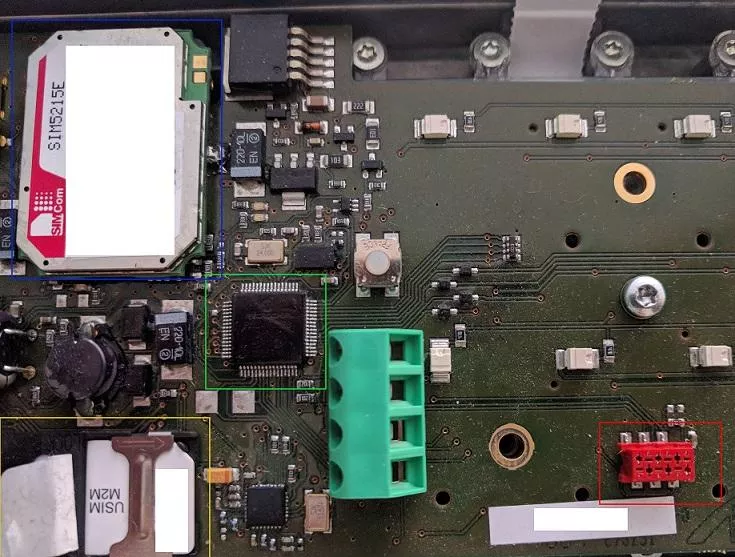
By looking on the Printed Circuit Board (PCB) of the intercom, we can notice 4 interesting components:
- A SIM/USIM slot (yellow);
- The 3G modem (blue);
- The MCU (Microcontroller Unit) (green);
- A strange interface (red);
As pentesters, our first reflex is to identify the exposed interface. Many ways exist and for the most commonly used devices, such as routers, an invaluable resource is /dev/ttys0's blog. About IoT devices, this year at the French conference SSTIC, Damien Cauquil has also presented his feedback when attacking IoT devices that the the Bluetooth Low Energy, and techniques that could be used to identify interesting components on devices PCB.
Before doing anything, we need to identify the MCU family and its version. Even with good eyes and good light, this information is difficult to get but with persistence, its possible to decode the following writing: Microchip - PIC24FJ128 - GA006.
Then with that information we have to look for the documentation of this particular MCU, that could be found in the following PIC24FJ128GA010 family datasheet.
The targeted interface has 6 PINs. At first sight, we can think it is maybe a JTAG interface, but a continuity tests with a multimeter reveals something else. Indeed, this interface is connected to the following pins (which is completely different from the expected JTAG):
- PGC1 (pin 25);
- PGD1 (pin 16);
- Vdd (pin 38);
- /MCLR (pin 7);
- AVss (pin 19).
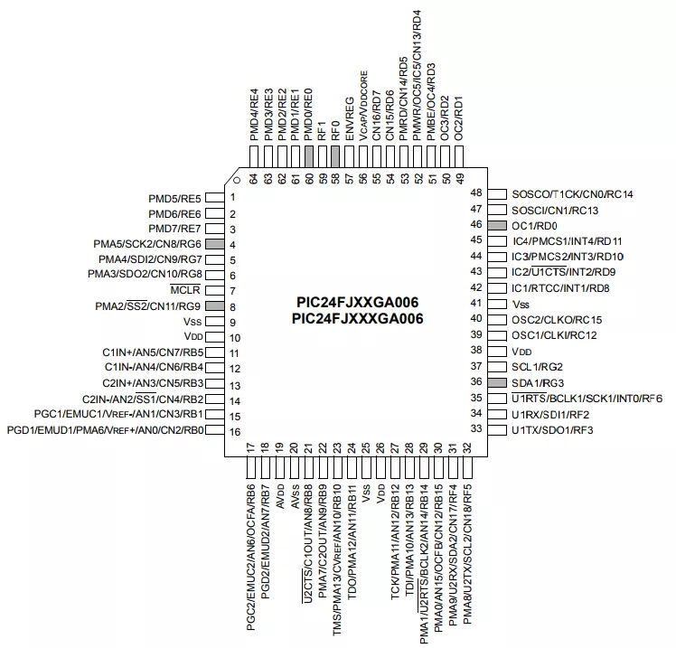
The MCU datasheet informs us that those pins are meant for "In-Circuit Debugger and ICSP Programming Clock". To communicate on this port a PICKit 3 In-Circuit Debugger can be used (~20€).
We can then connect the PICKit 3 to the intercom debugging and programming interface as follows:
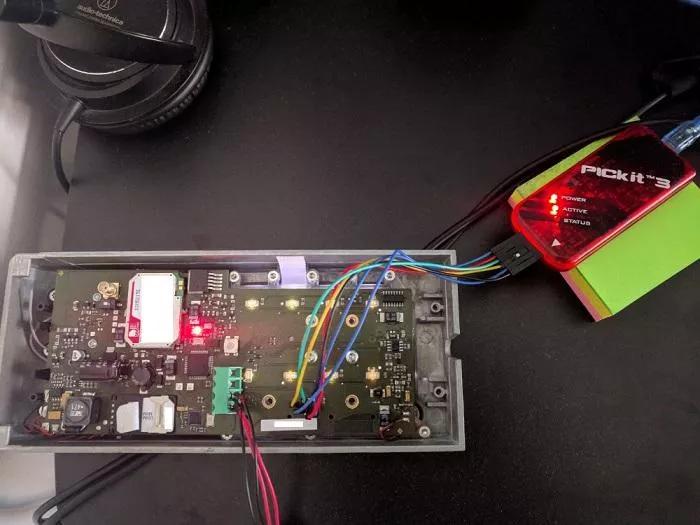
The setup is now complete and we can dump the firmware.
Dumping and analysing the firmware
The PICKit 3 In-Circuit Debugger can be used with an IDE software called "MPLAB X" to debug, program, and to read/dump the memory (the firmware).
The software is freely available at: http://www.microchip.com/mplab/mplab-x-ide.
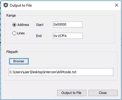
With this software, we are able to read the memory, and export it to a file we can name IntercomFirmware.hex and get data in Intel Hex format as follows:
$ cat IntercomFirmware.hex
:020000040000FA
:100000000A40040001000000344001000A0400001E
[...]
The content of sections can be read with objdump:
$ objdump -s IntercomFirmware.hex

IntercomFirmware.hex:     file format ihex

Contents of section .sec1:
 0000 0a400400 01000000 34400100 0a040000  .@......4@......
 0010 3a040000 6a040000 9a040000 34400100  :...j.......4@..
 0020 34400100 34400100 ca040000 fa040000  4@..4@..........
 0030 2a050000 5a050000 34400100 8a050000  *...Z...4@......
[...]
But also exported with objcopy:
$ objcopy -I ihex IntercomFirmware.hex -O binary Intercom.bin
By quickly looking for strings in the binary, we can see interesting AT commands sent by the MCU to the 3G modem:
0001ab00  02 00 78 00 00 80 fa 00  00 00 06 00 41 54 00 00  |..x.........AT..|
0001ab10  2b 4e 00 00 45 54 00 00  43 4c 00 00 4f 53 00 00  |+N..ET..CL..OS..|
0001ab20  45 0d 00 00 00 2b 00 00  43 4c 00 00 49 50 00 00  |E....+..CL..IP..|
0001ab30  3a 20 00 00 22 1b 00 00  df 22 00 00 2c 1b 00 00  |: .."...."..,...|
0001ab40  ef 00 00 00 45 52 00 00  52 4f 00 00 52 00 00 00  |....ER..RO..R...|
0001ab50  41 54 00 00 2b 43 00 00  4f 50 00 00 53 3d 00 00  |AT..+C..OP..S=..|
0001ab60  33 2c 00 00 32 0d 00 00  00 41 00 00 54 2b 00 00  |3,..2....A..T+..|
0001ab70  43 4f 00 00 50 53 00 00  3f 0d 00 00 00 2b 00 00  |CO..PS..?....+..|
0001ab80  43 4f 00 00 50 53 00 00  3a 20 00 00 1b ef 00 00  |CO..PS..: ......|
0001ab90  2c 1b 00 00 ef 2c 00 00  22 1b 00 00 df 22 00 00  |,....,.."...."..|
0001aba0  2c 1b 00 00 ef 00 00 00  2b 43 00 00 4f 50 00 00  |,.......+C..OP..|
0001abb0  53 3a 00 00 20 30 00 00  00 41 00 00 54 2b 00 00  |S:.. 0...A..T+..|
0001abc0  43 4f 00 00 50 53 00 00  3d 34 00 00 2c 32 00 00  |CO..PS..=4..,2..|
0001abd0  2c 1b 00 00 eb 2c 00 00  32 0d 00 00 00 41 00 00  |,....,..2....A..|
0001abe0  54 2b 00 00 43 53 00 00  51 0d 00 00 00 2b 00 00  |T+..CS..Q....+..|
0001abf0  43 53 00 00 51 3a 00 00  20 1b 00 00 ef 2c 00 00  |CS..Q:.. ....,..|
0001ac00  1b ef 00 00 00 41 00 00  54 2b 00 00 43 52 00 00  |.....A..T+..CR..|
0001ac10  45 47 00 00 3f 0d 00 00  00 2b 00 00 43 52 00 00  |EG..?....+..CR..|
0001ac20  45 47 00 00 3a 20 00 00  1b ef 00 00 2c 1b 00 00  |EG..: ......,...|
[...]
AT commands present in the blob:
- PLMN selection:
AT+COPS; - Network registration:
AT+CREG.
Moreover, we can notice another interesting blob:
0001b3e0  ef 3a 00 00 1b ef 00 00  00 41 00 00 54 41 00 00  |.:.......A..TA..|
0001b3f0  0d 00 00 00 41 54 00 00  2b 43 00 00 52 45 00 00  |....AT..+C..RE..|
0001b400  47 3d 00 00 30 0d 00 00  00 41 00 00 54 2b 00 00  |G=..0....A..T+..|
0001b410  4e 45 00 00 54 4f 00 00  50 45 00 00 4e 3d 00 00  |NE..TO..PE..N=..|
0001b420  22 54 00 00 43 50 00 00  22 2c 00 00 38 30 00 00  |"T..CP..",..80..|
0001b430  0d 00 00 00 61 6c 00 00  72 65 00 00 61 64 00 00  |....al..re..ad..|
0001b440  79 20 00 00 6f 70 00 00  65 6e 00 00 65 64 00 00  |y ..op..en..ed..|
0001b450  00 41 00 00 54 2b 00 00  49 50 00 00 41 44 00 00  |.A..T+..IP..AD..|
0001b460  44 52 00 00 0d 00 00 00  41 54 00 00 2b 54 00 00  |DR......AT..+T..|
0001b470  43 50 00 00 43 4f 00 00  4e 4e 00 00 45 43 00 00  |CP..CO..NN..EC..|
0001b480  54 3d 00 00 22 67 00 00  73 6d 00 00 2e XX 00 00  |T=.."g..sm...X..|
0001b490  XX XX 00 00 XX XX 00 00  XX XX 00 00 XX XX 00 00  |XX..XX..XX..XX..|
0001b4a0  2e 69 00 00 6e 66 00 00  6f 22 00 00 2c 36 00 00  |.i..nf..o"..,6..|
0001b4b0  30 30 00 00 30 31 00 00  0d 00 00 00 41 54 00 00  |00..01......AT..|
0001b4c0  2b 54 00 00 43 50 00 00  43 4f 00 00 4e 4e 00 00  |+T..CP..CO..NN..|
0001b4d0  45 43 00 00 54 3d 00 00  22 67 00 00 73 6d 00 00  |EC..T=.."g..sm..|
0001b4e0  2e XX 00 00 XX XX 00 00  XX XX 00 00 XX XX 00 00  |.X..XX..XX..XX..|
0001b4f0  6e 65 00 00 2e 69 00 00  6e 66 00 00 6f 22 00 00  |XX...i..nf..o"..|
0001b500  2c 35 00 00 35 35 00 00  35 1b 00 00 ff 0d 00 00  |,5..55..5.......|
0001b510  00 43 00 00 4f 4e 00 00  4e 45 00 00 43 54 00 00  |.C..ON..NE..CT..|
0001b520  20 46 00 00 41 49 00 00  4c 00 00 00 41 54 00 00  | F..AI..L...AT..|
0001b530  2b 54 00 00 43 50 00 00  43 4f 00 00 4e 4e 00 00  |+T..CP..CO..NN..|
0001b540  45 43 00 00 54 3d 00 00  22 39 00 00 31 2e 00 00  |EC..T=.."9..1...|
0001b550  31 32 00 00 31 2e 00 00  XX XX 00 00 XX XX 00 00  |12..1...XX...X..|
0001b560  37 22 00 00 2c 35 00 00  35 35 00 00 35 1b 00 00  |7"..,5..55..5...|
[...]
That reveals the endpoints we are looking at:
AT+TCPCONNECT="gsm.XXXXXXXXX.info",60001;AT+TCPCONNECT="gsm.XXXXXXXXX.info",5555(last number "6" is missing);AT+TCPCONNECT="91.121.XX.XX",5555(last number "6" is missing).
With some difficulties we are also able to spot the intercom ID number XX4015:
00017d80 15 40 XX 00 80 4a 78 00 63 00 60 00 66 40 78 00 |.@X..Jx.c.`.f@x.|
So here we have been able to get interesting information we can already use to begin our tests. But compared to the inteception technique, there is some missing contents like the payload of queries.
To go further, we can try to analyze the assembly code.
Further work
Unfortunatelly for us, trying to disassemble the code with IDA, metasm, RetDec, or radare2 does not product satisfying results. Indeed, IDA support PIC 12XX, PIC 14XX, PIC 16XXX and also 16-bit microcontrollers like the PIC 16XX family, but does not recognize any of PIC 24XX family. Also radare2, known to support exotic architectures, only supports PIC 14XX and PIC 16XX. Metasm on the other hand seems to support PIC 16XX only and its concurrent Miasm2 does not even know what PIC is. On the overside RetDec only supports 32-bit architectures like PIC32, but still there is not support for PIC24.
After spending quite a lot of time looking for all possible reverse engineering tools (this reminds us the opening keynote of Halvareflake at SSTIC 2018), it seems that MAPLAB X IDE is the only software capable of reading the assembly of this firmware without spending too much time writing an engine for IDA, miasm, metasm, etc.
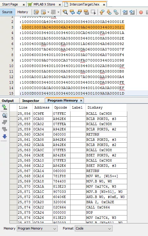
So using the official IDE, we are able to read the memory of the intercom and decode its assembly code as follows:
By the way, it is also possible to get the configuration bits of the MCU. This information could be helpful to check security configuration features during an intrusion test, or configuration test:
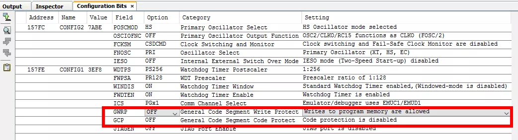
We can see that the JTAG is clearly disabled, but there is no code nor writing protection activated. That explains also why we are able to dump the MCU's memory.
But reading the code in the IDE is not really comfortable, and luckily MAPLAB X IDE allows to export the disassembled content to a text file:
Open the exported file in your favorite text editor:
     Line    Address    PSV Address      Data   Opcode  Label      DisAssy
      1       00000       ----           ----   04400A            GOTO 0x1400A
      2       00002       ----           ----   000001            NOP
      3       00004       ----           ----   014034            GOTO W4
      4       00006       ----           ----   00040A            NOP
      5       00008       ----           ----   00043A            NOP
      6       0000A       ----           ----   00046A            NOP
      7       0000C       ----           ----   00049A            NOP
[...]
Looking at the first instruction suggest us to go to address 0x1400A and given the numbers of NOPs, and GOTO W4 instructions, the program is probably starting here 0x1400A:
    40966    1400A      ----        ----  20850F         MOV #0x850, W15
    40967    1400C      ----        ----  225AA1         MOV #0x25AA, W1
    40968    1400E      ----        ----  880101         MOV W1, SPLIM
    40969    14010      ----        ----  A94044         BCLR CORCON, #2
    40970    14012      ----        ----  202B81         MOV #0x2B8, W1
    40971    14014      ----        ----  E00001         CP0 W1
    40972    14016      ----        ----  320003         BRA Z, 0x1401E
    40973    14018      ----        ----  200011         MOV #0x1, W1
    40974    1401A      ----        ----  8801A1         MOV W1, PSVPAG
    40975    1401C      ----        ----  A84044         BSET CORCON, #2
    40976    1401E      ----        ----  200000         MOV #0x0, W0
    40977    14020      ----        ----  200001         MOV #0x0, W1
    40978    14022      ----        ----  700001         IOR W0, W1, W0
    40979    14024      ----        ----  320002         BRA Z, 0x1402A
    40980    14026      ----        ----  020000         CALL 0x0
    40981    14028      ----        ----  000000         NOP
    40982    1402A      ----        ----  024036         CALL 0x14036
[...]
Here an important work is needed to decode the assembly and identify the cryptographic primitives used to encrypt the uploaded payload previously captured.
Hopefully we will have the opportunity to continue attacking this intercom again (and write another blog post about it). Moreover, by chance, an engine for PIC24 micro-controllers will be pop to trace the code more quickly.
Conclusion
We saw two different techniques that could help us find endpoints used by IoT devices. The two methods can be independent, but should be considered as complementary. Indeed, hardware focused attacks can be time consuming when it comes to understanding a firmware of a very exotic architecture not supported by currently available tools. Also, auditing the RF side could help to identify corner cases and other interesting parts of the firmware. The work is not finished yet, and hopefully the rest of the intercom firmware analysis will be the subject of another interesting adventure.
We should remember that all these techniques can be used against other devices using the mobile network, and you will be surprised by the sheer number of these devices and the sensitive content exchanged...
So stay tuned on radio waves! ;)